
90-130W Audio Amplifier using 2N3773
The audio amplifier circuit is designed to deliver high power output, specifically targeting applications that require robust audio amplification. The amplifier can be configured to provide either 90W or 130W output, depending on the number of output transistors used. With two output transistors, the amplifier achieves a maximum output of 90W, while utilizing four output transistors allows it to reach the full 130W output capability.
The PCB layout is critical for ensuring proper thermal management and efficient signal flow. The designation T3 indicates a specific location on the heatsink where thermal dissipation components are mounted, which is essential for maintaining the reliability and performance of the amplifier under high load conditions.
The component specifications include resistors with different power ratings and values, which play a crucial role in setting the biasing and gain of the amplifier circuit. R1, with a value of 120K ohms and a power rating of 1/4W, is likely used in the input stage for signal conditioning. R2, at 3.3K ohms and rated for 1/2W, may serve as a feedback resistor, influencing the overall gain of the amplifier. R3, with a value of 5.6K ohms and a power rating of 1/4W, could be part of the biasing network, ensuring optimal operation of the output transistors. Finally, R4, also at 3.3K ohms and rated for 1/4W, may have a similar role to R2, providing stability and linearity in the amplifier's performance.
In summary, this audio amplifier circuit is designed for high output power with careful consideration of component selection and PCB layout to ensure effective thermal management and signal integrity, making it suitable for demanding audio applications.Audio Amplifier 100W or 130W Outputshould be2(out=90W) or 4(out=130W) audio power transistors. PCB and layout Use T3 on Heatsink Component Ref./Value Type R1 120K 1/4W Resistor R2 3K3 1/2W Resistor R3 5K6 1/4W Resistor R4 3K3 1/4W Resistor.. 🔗 External reference
Related Circuits
This is a circuit that generates white noise, rolled-off to drive earphones or a small speaker. White noise creates is a "rushing" sound, which sounds something like air rushing by your ear(s). White noise would be flat with frequency,...
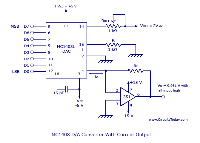
Monolithic/Hybrid Digital to Analog Converters using MC 1408 IC, SE/NE 5018, Specifications and Applications. Monolithic and hybrid digital-to-analog converters (DACs) are integral components in various electronic systems, facilitating the conversion of digital signals into corresponding analog voltages or currents. The...
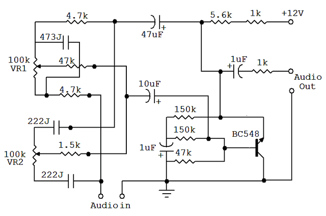
An audio equalizer circuit is utilized to modify the frequency response of an audio signal. This particular equalizer circuit is designed for adjusting the bass and treble (tone) levels of an audio amplifier. To integrate this equalizer circuit with...
For beginners in microcontroller projects who are unsure where to start, this project serves as one of the simplest options available. It provides a clear understanding of programming a microcontroller. Often, one may glance at a watch and ponder,...
An astable multivibrator is an electronic device that continuously alternates between two states in its output. When one state is high, the other is low. This characteristic is useful for generating a continuous stream of pulses without the need...

R1 is a 15k ohm resistor. An NTC thermistor rated at 10k ohm, available at Radio Shack in the United States, is utilized. P1 is a 10k ohm potentiometer that sets the low speed (voltage) of the fans at...
Warning: include(partials/cookie-banner.php): Failed to open stream: Permission denied in /var/www/html/nextgr/view-circuit.php on line 713
Warning: include(): Failed opening 'partials/cookie-banner.php' for inclusion (include_path='.:/usr/share/php') in /var/www/html/nextgr/view-circuit.php on line 713