
bh1417f fm stereo transmitter electronic project
The BH1417F FM stereo transmitter IC is a versatile component that integrates both the stereo modulation and transmission functions within a single chip. The stereo modulator's ability to generate composite signals is essential for maintaining audio quality during transmission. The MAIN signal carries the primary audio content, while the SUB signal provides additional stereo information, and the pilot signal, generated from the 38kHz oscillator, is crucial for demodulation at the receiver end.
The circuit's design allows for a range of applications, particularly in personal broadcasting scenarios where users wish to transmit audio wirelessly within a limited distance. The effective range of approximately 20 meters makes it suitable for home use, allowing music to be streamed to various locations within a residence or small venue without the need for extensive wiring.
The construction of the L1 coil is a critical aspect of the transmitter's performance. The specified 2.5 turns of enamelled copper wire ensure that the coil is capable of generating the necessary inductance for efficient operation. The use of an F29 ferrite slug enhances the coil's magnetic properties, improving the overall efficiency of the transmitter. The option to use a commercially available variable coil provides flexibility in tuning the transmitter for optimal performance, allowing users to adjust the frequency as needed to avoid interference with other signals.
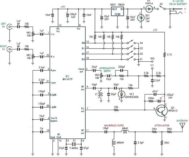
Overall, this circuit design exemplifies an effective approach to FM transmission, combining ease of use with quality audio performance, making it a valuable tool for hobbyists and professionals alike in the field of wireless audio broadcasting.This stereo FM stereo modulator circuit use the BH1417F FM stereo transmitter IC which consists of a stereo modulator for generating stereo composite signals and a FM transmitter for broadcasting a FM signal on the air. The stereo modulator generates a composite signal which consists of the MAIN, SUB, and pilot signal from a 38kHz oscillator.
This BH1417F stereo FM transmitter is capable of broadcasting good quality signals over a range of about 20 meters and is ideal for broadcasting music from a CD player or from any other signal source so that it can be picked up in another location. L1 coil comprises 2. 5 turns of 0. 5 - 1mm enamelled copper wire (ECW) wound onto a tapped coil former fitted with an F29 ferrite slug. Alternatively, you may also use any commercially made 2. 5 turns variable coil. 🔗 External reference
Related Circuits
The 900 Hz tone is generated using an LC oscillator. The inductive component, "L," is provided by the inductance of the oscillator's output coupling transformer T1. This configuration is a variation of one of the two standard Hartley oscillator...
When a couple moved into their small apartment in San Francisco, they wanted to create a compact liquor cabinet and wine rack. After a visit to IKEA, they acquired a bookshelf that could be easily transformed into a stylish...
The Muntz one-tube design can be significantly enhanced by incorporating an audio preamplifier stage. This modification increases sensitivity, allowing for full modulation with lower-level signal sources, such as certain older CD players and ceramic phono cartridges. Additionally, implementing negative...
A digital micro-ohm meter is essential for assessing the condition of shunts used in the Electrochemical Analysis & Diagnostics Laboratory (EADL) at Argonne National Laboratories. A shunt is essentially a small resistor utilized for current measurement. The micro-ohmmeter will...

The thermistor RT, along with resistors R1, R2, R3, and variable resistor RP1, creates a temperature measurement bridge. At a temperature of 20°C, the configuration of R1, R3, and the adjustment of RP1 enables the bridge to maintain balance....
A simple proximity detector can be created using this electronic circuit. This circuit responds to the presence of a conductive object within a specific range. The sensitivity of the circuit can be adjusted with potentiometer P1 to achieve the...