
Bi-directional motor
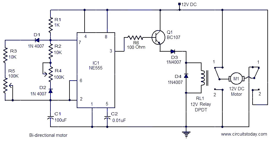
The circuit employs an NE555 timer configured in astable mode, generating a continuous square wave output that toggles between high and low states. This output controls the operation of a relay, which in turn manages the direction of the DC motor. The relay acts as a switch, allowing the circuit to reverse the polarity of the voltage applied to the motor, thereby enabling bidirectional control.
The timing components, including resistors R1, R2, R3, R4, R5, and capacitor C1, determine the frequency and duty cycle of the square wave. By adjusting the values of the potentiometers R4 and R5, the user can fine-tune the duration of the motor's operation in either direction, providing flexibility in applications requiring variable speed or run time.
Transistor Q1 serves as a switching device, amplifying the output signal from the NE555 timer to drive the relay coil. This arrangement ensures that the relay operates reliably without drawing excessive current from the timer output. The inclusion of diode D4 is crucial for protecting the circuit from back EMF generated by the relay coil when it is de-energized. This diode allows the inductive kickback to dissipate safely, preventing potential damage to the transistor and other components.
Overall, this circuit is suitable for applications requiring simple motor control, such as in robotics, automated systems, or small-scale machinery, where bidirectional motor operation is necessary. The straightforward design and adjustable timing make it an accessible choice for both hobbyists and professionals in the field of electronics.This is a simple and easy to construct circuit that can be used to provide a bidirectional drive to a DC motor. The circuit operation is straight forward. Output of an astable mutivibrator based on IC1 (NE555) is used to control the relay RL1 driving the motor.
The motor is connected between the two poles of the relay contacts. The relay contacts are so wired as to reverse the DC supply to the motor when the contacts changeover. The astable multivibrator produces a square wave at the output with its high time given by 0. 69(R1+R3+R5)C1 and low time given by 0. 69(R1+R2+R4)C1. The high and low times can be varied by varying potentiometers R4 and R5. For the given values the high and low times can be adjusted between 1S and 8S separately. When the IC1 output is low, the relay is de energised and the relay contacts are in position 1-1 with the result that A terminal of the motor is positive and motor runs in one direction. The IC1 output is high the relay is energised and the contacts changeover to position 2-2. Now the terminal B of the motor becomes positive and motor runs in the opposite direction. The transistor Q1 is used to drive the relay according to the output from IC1. The diode D4 acts as freewheeling diode. 🔗 External reference
Related Circuits
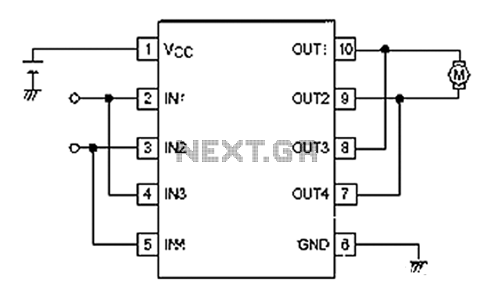
A simple motor control project for forward and backward drive can be implemented using the LB1948M motor driver IC, which features two channels for motor control. The LB1948M is an ideal choice for 12V motor drive systems and can...
Camping today often requires bringing various electronic devices for daily use or entertainment. Typically, a charged lead-acid battery and a power inverter are utilized to ensure a well-organized holiday where family members can enjoy their electronic gadgets. It is...
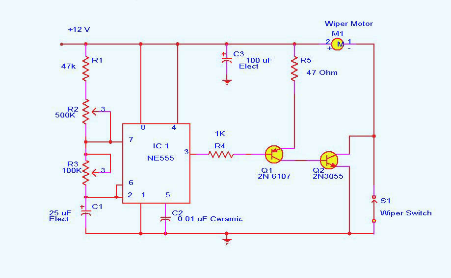
DC motor control circuit using NE555. The 555 timer circuit has numerous applications. For those unfamiliar with its functionalities, an authoritative book can provide valuable insights. CircuitsToday offers an online store featuring reviews of three highly recommended books that...
Stepper motors are a recurring subject. This circuit converts a clock signal from a square wave generator into signals with a 90-degree phase shift. Stepper motors are widely used in applications requiring precise control of angular position, speed, and acceleration....
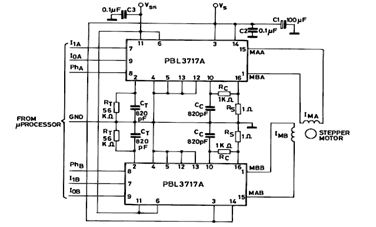
The diagram below illustrates a Two Phase Bipolar Stepper Motor Driver utilizing the PBL3717A. It depicts two PBL3717A integrated circuits (ICs) that control and drive two bipolar stepper motors. The Two Phase Bipolar Stepper Motor Driver circuit is designed to...
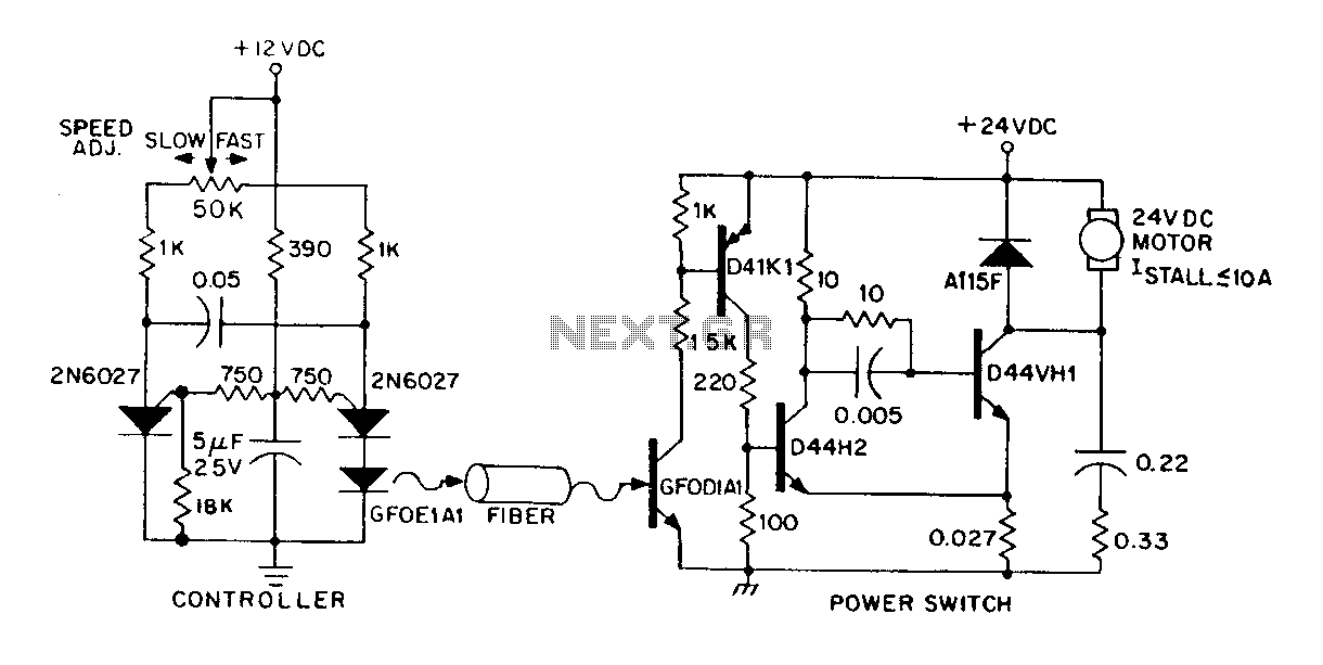
A DC power supply can be controlled through an optical fiber. The circuit includes a small DC motor (1/12 hp) that offers an isolated speed control channel. The control logic operates as an independent module, consuming 300 mW of...