
bicycle back safety light
The circuit operates at a low voltage, typically around 3V, making it suitable for battery operation. The use of high-efficiency LEDs ensures that the device consumes minimal power, extending battery life, which is particularly beneficial for outdoor applications such as cycling and jogging. The configuration of the LEDs in two series allows for an engaging visual effect that enhances visibility during low-light conditions.
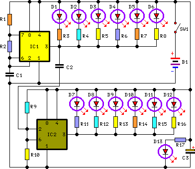
The astable multivibrator configuration of the 555 IC is crucial for generating the flashing effect. It produces a square wave signal that alternates between high and low states, effectively controlling the LEDs' on and off states. The first set of LEDs (D1-D6) is connected directly to the positive supply rail, allowing them to flash in synchrony with the output of the first 555 IC. Meanwhile, the second 555 IC serves to trigger and invert the signal for the second set of LEDs (D7-D12), creating the alternating flashing pattern that simulates a rotating light.
The inclusion of the permanently lit LED (D13) at the center serves both a functional and aesthetic purpose, providing a constant point of illumination that enhances the overall visibility of the device. This design choice is particularly advantageous for safety applications, ensuring that the device remains noticeable even when the flashing LEDs are not active.
Overall, the circuit's thoughtful design, combining efficient components and strategic layout, results in a reliable and visually appealing lighting solution suitable for various outdoor activities.This circuit has been designed to provide a clearly visible light, formed by 13 high efficiency flashing LEDs arranged in a pseudo-rotating order. Due to low voltage, low drain battery operation and small size, the device is suitable for mounting on bicycles as a back light, or to put on by jogger/walkers.
IC1 is a CMos version of the 555 IC wired as an astable multivibrator generating a 50% duty-cycle square wave at about 4Hz frequency. At 3V supply, 555 output (pin 3) sinking current operation is far better than sourcing, then LEDs D1-D6 are connected to the positive supply rail. In order to obtain an alternate flashing operation, a second 555 IC is provided, acting as a trigger plus inverter and driving LEDs D7-D12.
D13 is permanently on. The LEDs are arranged in a two series display as shown below, with a center LED permanently on. This arrangement and the alternate flashing of the two series of LEDs provide a pseudo-rotating appearance. 🔗 External reference
Related Circuits

The 555 timer IC is connected for Astable Operation, the clock pulses are fed to the 4017 IC via the 10K resistor. The 4017 is a 10 stage counter, each of the outputs is connected to the appropriate LED,...

How to turn on equipment by sending SMS `1111` to switch it ON and switch off the equipment by sending SMS `0000`. The GSM switch will receive instructions for either load 1 (L1), load 2 (L2), load 3 (L3),...

This article discusses the design of an LED driver for automotive rear lights. It demonstrates that dimming is most effectively accomplished using pulse-width modulation (PWM) in conjunction with an LED driver integrated circuit (IC) that removes the requirement for...
The inquiry pertains to the connection of lights that flash when a phone rings. This feature is particularly beneficial in noisy environments, such as workshops, where hearing the phone may be difficult. A device designed for this purpose is...

The circuit described here can be built and used in a vehicle for an automatic dipping and dimming operation of the headlamps in response to intense lights coming from opposite vehicle headlamps. This situation is often encountered while driving...

The PIC microcontroller is capable of controlling a motor after each beat, with the option to bypass certain beats using pushbuttons. The rotation speed and duration can also be adjusted within specified limits to prevent register overflow or underflow....