
Voltage controlled amplifier
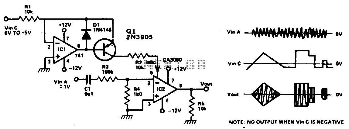
The operational amplifier circuit described operates as a differential amplifier, where the input signals are applied to the inverting (pin 2) and non-inverting (pin 3) terminals. The differential voltage of ±10 mV indicates that the circuit is designed for high precision, allowing it to amplify small voltage differences effectively. The additional input at pin 5 serves as a control mechanism, where the injected current (Iabc) modulates the gain of the amplifier. This feature is particularly useful in applications requiring dynamic adjustment of gain based on varying input conditions.
The output signal at pin 6 is a function of the differential input voltage and the gain set by the current at pin 5. This relationship can be expressed mathematically as V_out = Gain × V_diff, where V_diff is the voltage difference between pins 2 and 3. The linear control of gain ensures that the output signal remains proportional to the input, which is crucial for maintaining signal integrity, especially in audio applications.
Inserting an audio signal into this circuit allows for the amplification of audio frequencies, making it suitable for various applications such as audio processing, signal conditioning, and other electronic systems where precise signal amplification is required. The design ensures minimal distortion and high fidelity in the output, which is essential for high-quality audio performance.This circuit is basically an op amp with an nal (±10 mV) between pin 2 and 3 and by extra input at pin 5. A current Iabc is injected controlling the current on pin 5, the level of the into this input and this controls the gain of the signal output (pin 6) is controlled, device linerly
Thus by inserting an audio sig-. 🔗 External reference
Related Circuits
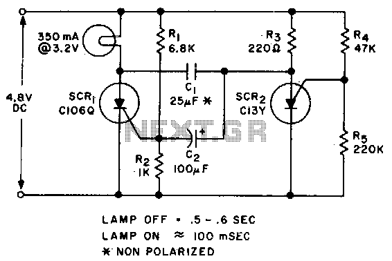
Applying voltage to the circuit triggers SCR1. With SCR1 on, the voltage on the anode of SCR2 rises until SCR2 triggers to commutate SCR1. The voltage on the gate of SCR1 will swing negative at this time, and only...
The ICM7226 is a fully integrated Universal Counter and LED Display driver. It combines a high-frequency oscillator, a decade timebase counter, an 8-decade data counter and latches, a 7-segment decoder, digit multiplexer, and segment and digit drivers, which can...
The supply voltage should be about +/- 35 Volts at full load, which will let this little guy provide a maximum of 56 Watts (rated minimum output at 25 degrees C). To enable maximum power, it is important to...
This small circuit is a linear amplifier for driving small UHF TV transmitters. Its gain is 7 dB and can amplify a signal between 450-800 MHz. You can drive the circuit with 1 to 1.5 Watts signal. Better use...
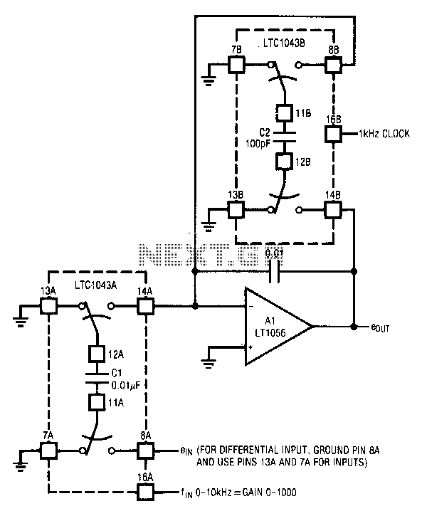
The circuit utilizes the LTC1043 in a variable gain amplifier configuration, which offers continuously adjustable gain, gain stability of 20 ppm/°C, and supports both single-ended and differential inputs. Two separate LTC1043 devices are employed in the design. The LTC1043B...
This Class A amplifier utilizes a 12AU7-based valve preamp, delivering exceptionally pure sound quality. Although distortion levels are unknown, the amplifier exhibits a fine grain and delicately textured audio output. With an output of only one watt, it requires...