
binary clock
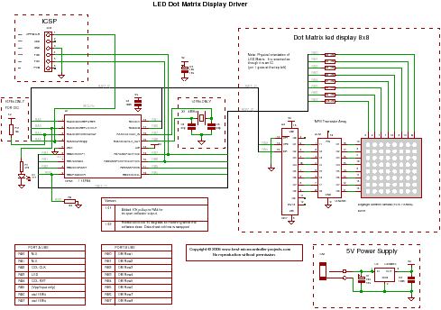
To design a binary clock using a PIC microcontroller, the circuit will primarily consist of the microcontroller, an LED matrix, and multiplexing circuitry. The PIC microcontroller will serve as the central processing unit, responsible for generating the binary time signals and controlling the display.
The LED matrix will be arranged in a grid format, typically 8x8 or 5x7, where each LED represents a binary digit (bit) of the time. The microcontroller will output signals to the LED matrix through a set of GPIO pins. Multiplexing is employed to minimize the number of pins required for driving the matrix. In this configuration, only a subset of the LEDs is activated at any given time, cycling through the rows or columns rapidly enough to create the illusion of a fully lit display.
The binary clock will represent time in hours, minutes, and seconds using binary-coded decimal (BCD) format. Each segment of time will be displayed in binary form on the LED matrix, with specific bits lighting up to indicate the current time. The microcontroller will need to keep track of the time using an internal timer or an external real-time clock (RTC) module to ensure accurate timekeeping.
The circuit will also require a power supply, typically 5V, to drive the microcontroller and the LED matrix. Additional components may include resistors for current limiting to the LEDs, and possibly capacitors for power stabilization. The program code for the PIC microcontroller will include routines for reading the time, converting it to binary, and controlling the multiplexing of the LED matrix.
This design offers an engaging and visually appealing way to display time, while also providing an opportunity to learn about binary numbers, microcontroller programming, and circuit design.How to make a binary clock using a PIC microcontroller using multiplexing to drive an LED matrix.. 🔗 External reference
Related Circuits
This precise one-pulse-per-second clock is constructed using a few common components and is driven by a 50 or 60 Hertz mains supply, without any direct connection to it. It produces a beep or metronome-like click and/or a visible flash...
This circuit provides a digital square wave that can be viewed directly or used to drive other circuits. It used the CMOS 4047 Low-Power Monostable/Astable Multivibrator. As used in Tom Duncan's Adventures with Digital Electronics Book, to drive CMOS...
The following circuit illustrates a Cat and Dog Repellent Timer Circuit Diagram. Features include the capability to maintain a deep cycle battery charged by a solar panel. The Cat and Dog Repellent Timer Circuit is designed to provide a humane...
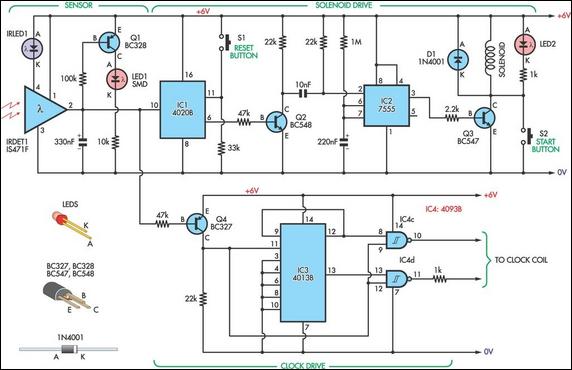
This design allows for the construction of an electromagnetically impulsed pendulum clock with a one-second beat. The prototype features a pendulum rod measuring 115 cm in length, with a bob adjusted to achieve a one-second beat. The pendulum is...
This is a programmable clock timer circuit that utilizes individual LEDs to indicate hours and minutes. Twelve LEDs can be arranged in a circle to represent the 12 hours of a clock face, and an additional 12 LEDs can...
Last year, I found a 31 day pendulum wall clock (disassembled) in a box of parts at a swap meet and decided to try and put it together and regulate it with a quartz crystal oscillator. The escapement part...
Warning: include(partials/cookie-banner.php): Failed to open stream: Permission denied in /var/www/html/nextgr/view-circuit.php on line 713
Warning: include(): Failed opening 'partials/cookie-banner.php' for inclusion (include_path='.:/usr/share/php') in /var/www/html/nextgr/view-circuit.php on line 713