
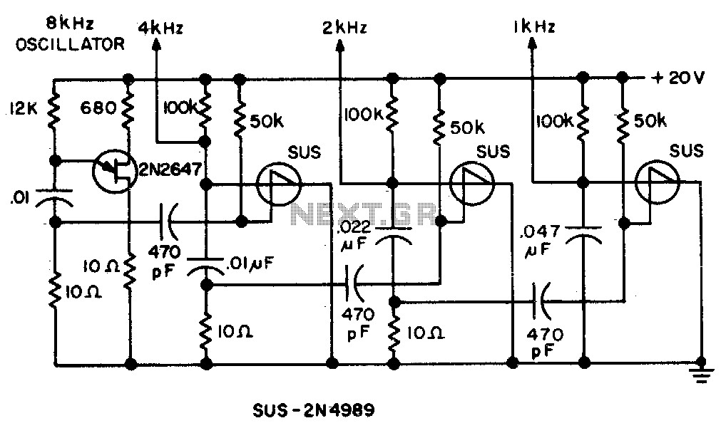
Binary divider chain

The circuit in question is designed to provide a simplified approach to signal processing by minimizing the number of components involved compared to conventional transistor flip-flops. This reduction in component count not only enhances reliability but also decreases the overall footprint of the circuit, making it suitable for compact applications.
The output at point "B" is noteworthy for its transient-free waveform, which indicates that the circuit is capable of delivering a stable signal without the usual spikes or dips that can occur during transitions. This characteristic is particularly beneficial in digital applications where signal integrity is paramount, such as in clock generation or data communication.
In terms of operation, the circuit likely employs a combination of passive and active elements, such as resistors, capacitors, and potentially a single active device like a CMOS or a specific type of logic gate that can achieve the desired flip-flop behavior. The careful selection of these components enables the circuit to maintain its performance while ensuring that the output remains clean and free from undesirable transients.
The transient-free nature of the output can be attributed to the circuit's design, which may include features such as proper timing control and feedback mechanisms that stabilize the output signal. This makes the circuit particularly useful in applications where precision and reliability are critical, such as in timing circuits or digital signal processing systems.
Overall, this circuit represents an efficient solution for applications requiring reliable signal processing with minimal component usage, ensuring both performance and space efficiency.This circuit uses fewer components than transistor flip flops Output at "B" gives a transient-free waveform.
Related Circuits
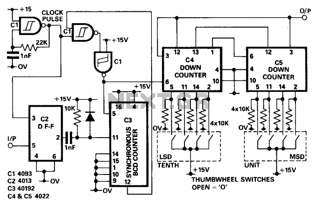
In applications where the period of the input pulses is uneven and a divider is required to accommodate a wide range of frequencies, a non-integer programmable pulse divider can be utilized. The D-type flip-flop (IC2) serves to synchronize the...
The circuit utilizes a 555 timer configured as a multivibrator, where the oscillation frequency is determined by resistors R1, R2, and capacitor C1. The frequency formula is given by fo = 1.443 / ((R1 + R2) * C1). The...
An idea proposed is to utilize a phase shift oscillator followed by an inverter to convert a sine wave into a square wave; however, this may be considered a rudimentary solution. There is also interest in schematics for a...
Spikes in the center of a sawtooth wave are eliminated in this circuit by triggering at specific intervals. This circuit is designed to mitigate unwanted spikes that occur in the center of a sawtooth waveform. The sawtooth wave, characterized by...
A new user expresses interest in lasers and has purchased an inexpensive red laser pointer and LED light combination keychain. The red laser pointer and LED light combination keychain is a compact and versatile device that serves multiple functions. The...
When a low or high input voltage in binary form, as obtained from the converter circuit (also provided in the article) fed by a digital voltmeter, is applied, the circuit generates a low pitch for binary 0 and a...