
Non-integer programmable pulse divider

The non-integer programmable pulse divider circuit is designed to effectively handle input signals with varying pulse periods, making it suitable for applications that require precise frequency division. The core component, the D-type flip-flop (IC2), plays a critical role in ensuring that the input signal is accurately synchronized with the clock signal, which is essential for reliable operation. The rising edge of the clock signal triggers IC2, which then outputs a high signal when the input is also high.
IC3, which functions as a counter, is reset to zero upon receiving the synchronized signal from IC2. It begins counting up from this reset state, allowing for the generation of an output pulse that is ten times the frequency of the input pulse. This amplification of the pulse count is vital for applications where increased output frequency is necessary.
Furthermore, to extend the counting capabilities, IC4 and IC5 are configured in a cascaded arrangement, forming a two-decade programmable down counter. This configuration allows for flexible programming of the output count, enabling the circuit to be tailored for specific frequency division requirements. The cascading of these counters enhances the overall functionality and versatility of the pulse divider, making it an essential component in various electronic applications where frequency manipulation is required.In applications where the period of the input pulses is uneven and the divider is required to cover a wide range of frequencies, the non-integer programmable pulse divider shown can be used. The purpose of the D-type flip-flop (IC2) is to synchronize the input signal with the clock pulse. When the clock pulse changes from low to high and the input is high, IC2 output goes high. Subsequently, IC3 resets to zero and starts counting up. The number of pulses at the output of IC3 is ten time the input pulse. IC4 and ICS are cascaded to form a two decade programmable down counter.
Related Circuits
The circuit samples the output of a multiplexer and provides the necessary current for driving a transfluxor in an analog-to-digital converter that generates a six-bit binary Gray code. -N. Aron and C. Granger, Analog-To-Digital Converter Uses Transfluxors, Electronics, 35:20,...
The speed of light has been measured using various ingenious methods. This note describes a conceptually simple and relatively easy-to-implement technique known as the time-of-flight optical pulse delay method. It utilizes a short (nanosecond) optical pulse and an oscilloscope...
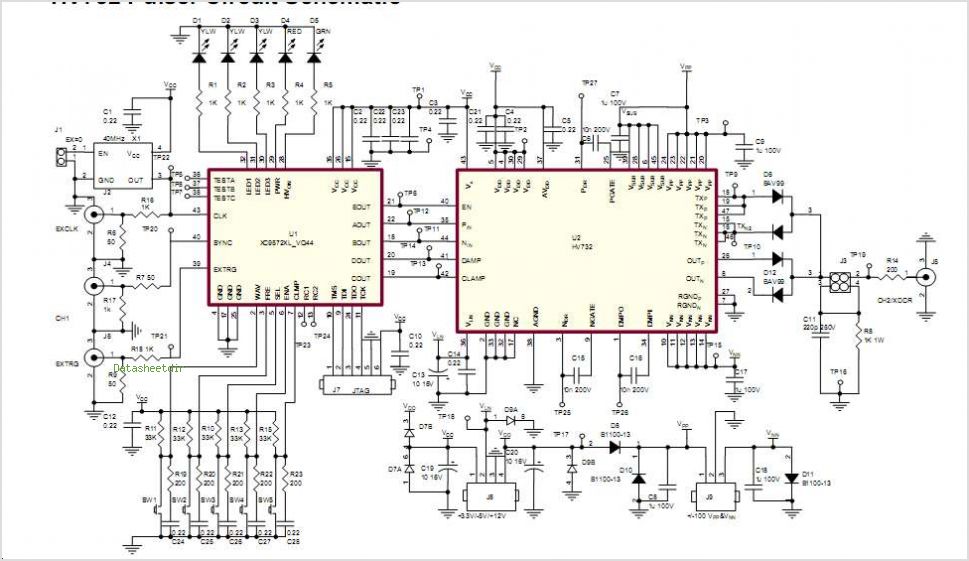
The Supertex HV7370 is a four-channel, high-speed, high-voltage ultrasound transmitter damper, while the HV748 is a four-channel, high-speed, high-voltage ultrasound transmitter pulser. Both integrated circuits (ICs) are intended for medical ultrasound imaging applications and can also be utilized as...
Power input is to a 7805 5 volt regulator. A pair of LEDs is connected between the 5 volt supply and ground, with current limiting resistors in series and one pin on the AT90S2313 shunts the current through one...
This project is offered totally free for those who are interested in it. I have tried to make this article as complete as possible, but I will not assume any liability for any errors or omissions in this article....
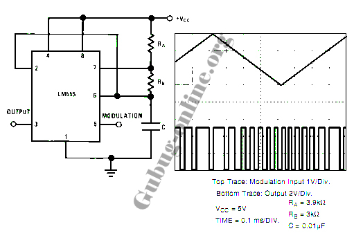
This design circuit for a pulse position modulator can be easily constructed using a 555 integrated circuit (IC). The pulse position modulator modulates the on-period while maintaining a fixed off-period. The circuit utilizes the 555 timer IC in astable mode...