
Bipolar stepper motor control with Picaxe and L293D
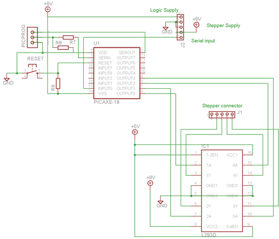
The schematic for the bipolar stepper motor control includes a microcontroller that communicates via a serial interface, allowing for precise control over the motor's operation. The bipolar stepper motor is characterized by its two coils, which must be energized in a specific sequence to achieve rotation. The microcontroller sends commands to a motor driver circuit, which handles the directional control and current flow to the coils.
In this configuration, the driver circuit typically employs H-bridge topology, enabling the reversal of current through the coils. This is essential for the bipolar motor operation, as it requires alternating current direction to step through its phases. The program running on the microcontroller includes algorithms for step control, allowing the motor to achieve desired speeds and positions based on input commands.
To ensure reliable operation, the schematic should incorporate necessary components such as current limiting resistors, flyback diodes for back EMF protection, and decoupling capacitors to stabilize the power supply. The choice of microcontroller and driver IC should be compatible with the required voltage and current specifications of the bipolar stepper motors.
Additionally, it is vital to consider the power supply requirements, as bipolar stepper motors typically require higher current ratings compared to unipolar motors. Proper heat dissipation measures should also be integrated into the design to prevent overheating of the driver circuit during prolonged operation.
In summary, the developed schematic and program provide a comprehensive solution for controlling bipolar stepper motors in robotic applications, enabling precise movement and positioning essential for the functionality of the robot arm.I`ve now got a schematic and program for running a bipolar stepper motor via a serial interface (just as for the unipolar case). This is important for the robot arm cause because two of the three steppers will be of the bipolar kind.
Where driving the unipolar stepper required only current `pushing` (ie all in. 🔗 External reference
Related Circuits
This compact circuit is designed to verify the basic functionality of an infrared remote control unit. It operates on the straightforward principle of connecting a piezo buzzer directly to an infrared (IR) receiver integrated circuit (IC). This approach is...
This digital volume control has no pot to wear out and introduces almost no noise in the circuit. Instead, the volume is controlled by pressing UP and DOWN buttons. This simple circuit would be a great touch to any...
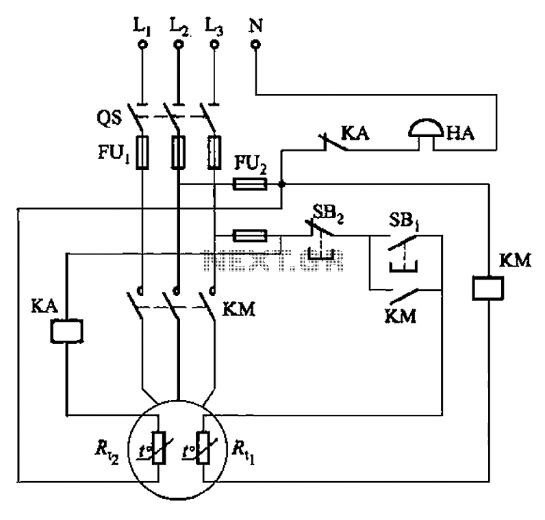
The circuit illustrated in Figure 4-2 employs two thermal resistors. One, designated as Rc, functions as overload protection, while the other, labeled Rt, serves as an alarm. The circuit in question integrates two thermal resistors to monitor temperature changes and...

The Atmega8 microcontroller from Atmel features numerous digital and analog input/output lines, making it an ideal choice for developing various measurement equipment. It is essential to have the GCC AVR programming environment installed, as outlined in the article "Programming...
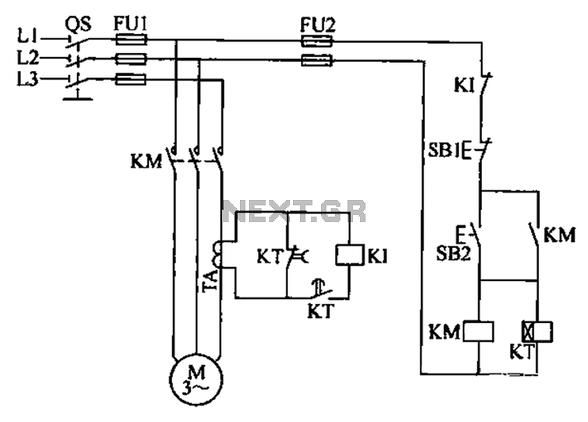
A three-phase electric motor overcurrent protection circuit. This example circuit utilizes a transformer to monitor the current, ensuring that the currents in the three-phase motor do not exceed normal operating levels. When the current exceeds the set threshold, the...
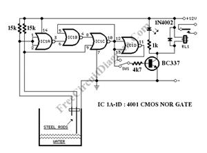
The circuit consists of a 555 timer IC configured as a multivibrator, which operates with two probes to measure the water level. When the capacitance between the probes indicates a high water level, the output from the 555 timer...
Warning: include(partials/cookie-banner.php): Failed to open stream: Permission denied in /var/www/html/nextgr/view-circuit.php on line 713
Warning: include(): Failed opening 'partials/cookie-banner.php' for inclusion (include_path='.:/usr/share/php') in /var/www/html/nextgr/view-circuit.php on line 713