
Blinker circuit 2

This circuit employs a pair of transistors, VTi and VTz, configured in a feedback loop facilitated by capacitive coupling through capacitor C. The operation relies on the triode characteristics of the transistors, which allow them to switch states based on the voltage levels across the capacitor. When VTi turns on, it allows current to flow through the circuit, charging the capacitor C. Once the capacitor reaches a certain voltage threshold, it triggers the turn-off of VTi and the turn-on of VTz. This process causes the light to flash.
The flash frequency is primarily determined by the time constant of the RC circuit formed by the capacitor C and the resistance in the circuit, which includes the load and any resistors present. The capacitance value of C, in conjunction with the current flowing through VTi, dictates how quickly the capacitor charges and discharges, thus influencing the overall flashing frequency. For the specified configuration, the circuit is designed to achieve a flashing frequency of around 20 flashes per minute, which can be adjusted by varying the capacitance or the current supplied to the circuit.
This design is particularly useful in applications where visual signaling is required, such as in decorative lighting or alert systems. The simplicity of the circuit allows for easy implementation and adjustment, making it a versatile choice for various electronic projects. Circuit shown in Figure 13-4. It uses triode control. Two transistors VTi, VTz by capacitive coupling C, so that they alternately turn on and off, so that H produce flash light s sparkle. Flash frequency capacity ,. and c is determined by the capacitance of the transistor VTi through current I. Press the element in FIG values lamp flash frequency of about 20 times per minute.
Related Circuits
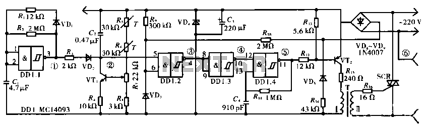
The circuit operates using a temperature stabilizer derived from the main oscillator (DD1.1), along with components including C1, R1, R2, and VD1. It incorporates a monostable multivibrator formed by R3, VD2, VT1, C2, R4, DD1.2, R7, and R8, as...
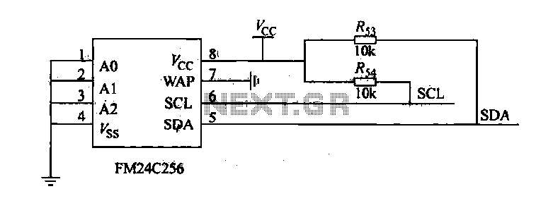
The FM24C256 is utilized as a slave interface circuit in an I2C bus configuration, with the address format specified in Table 27-3. The address pins A2, A1, and A0 are set to low; however, for extended storage capacity, adjustments...

This circuit has the advantage of transferring almost all the energy from the collapsing magnetic field of L2 to C2. In contrast, a typical Joule thief circuit allows some of this energy to return to the battery. This efficiency...
You may be familiar with this effect. You switch audio equipment such as an amplifier to a different input and there is a loud click or "thump" in the speaker system. Not all equipment is affected. Some high-end audio...
A rear fog lamp is mandatory for trailers and caravans to enhance visibility during foggy conditions. When the fog lamp is activated, the fog lamp of the towing vehicle must be turned off to prevent distracting reflections. To achieve...
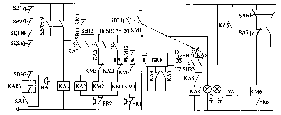
The operation control circuit is primarily managed by the button switch SB21. The contactor KM1, composed of the main contactor KM1, directly controls the operation of the main motor M1. The main motor M1 serves as the prime mover,...