
Household savings vegetable compartment temperature stabilizer circuit
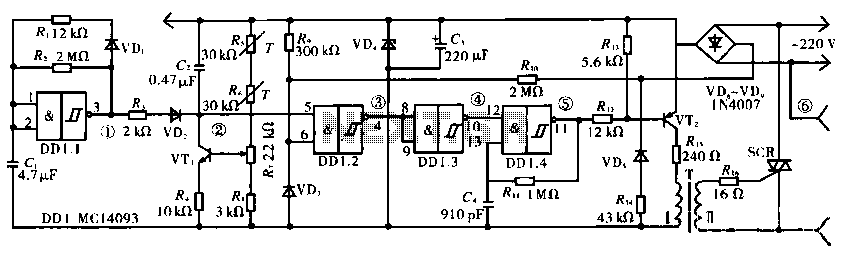
The temperature stabilizer circuit is designed to maintain a consistent temperature by adjusting the output based on feedback from thermal sensors. The main oscillator (DD1.1) generates a periodic signal that is processed through passive components C1, R1, and R2, which help filter and stabilize the signal. The diode VD1 ensures that the voltage levels remain within safe operating limits.
The monostable multivibrator, created with R3, VD2, VT1, C2, R4, and DD1.2, is triggered by the output from the main oscillator. This configuration allows for a single pulse output when activated, which can be used to control other elements in the circuit. Resistors R7 and R8 play a crucial role in setting the timing characteristics of the multivibrator.
Thermal resistors R5 and R6 are strategically placed to monitor temperature changes, providing feedback to the circuit to adjust its performance accordingly. The inverter (DD1.3) is used to invert the signal from the thermal sensors, ensuring that the control logic receives the correct input for further processing.
The strobe oscillator (DD1.4) generates a timing signal that synchronizes the operation of the triac circuit (VT2), which is responsible for controlling the power delivered to the load. Components R11 and C4 help in defining the frequency and duty cycle of the strobe signal.
For power management, the circuit utilizes a set of diodes (VD6 to VD9 and VD5) to rectify and regulate the input voltage, while R14 and VD4 assist in voltage stabilization. Capacitor C3 serves to filter out any noise in the power supply, ensuring that the circuit operates reliably under varying load conditions.
Overall, this circuit offers a robust solution for temperature stabilization, leveraging a combination of oscillators, multivibrators, and power management components to achieve precise control over heating elements or other temperature-sensitive devices.Circuit works: The temperature stabilizer from the main oscillator DD1.1, C1, R1, R2 and VD1, monostable multivibrator R3, VD2, VT1, C2, R4, DD1.2, R7, R8, thermal resistors R5, R6, inverter DD1.3, strobe oscillator DD1.4, R11, C4, triac circuit VT2, T, R12, R15, R16, and SCR power supply circuit VD6 ~ VD9, VD5, R14, VD4, C3, and so on.
Related Circuits
The following circuit illustrates the SCR BRY35 used in a simple radio control circuit. Features include a straightforward and efficient receiver for operation. The SCR BRY35 is a silicon-controlled rectifier designed to facilitate the control of high-power loads through low-power...

The circuit can incorporate a buffer gate at the input to ensure compatibility with TTL or other logic levels. This design is intended for a TTL 0V circuit to accommodate a 3.5V input signal swing. Additionally, it generates a...
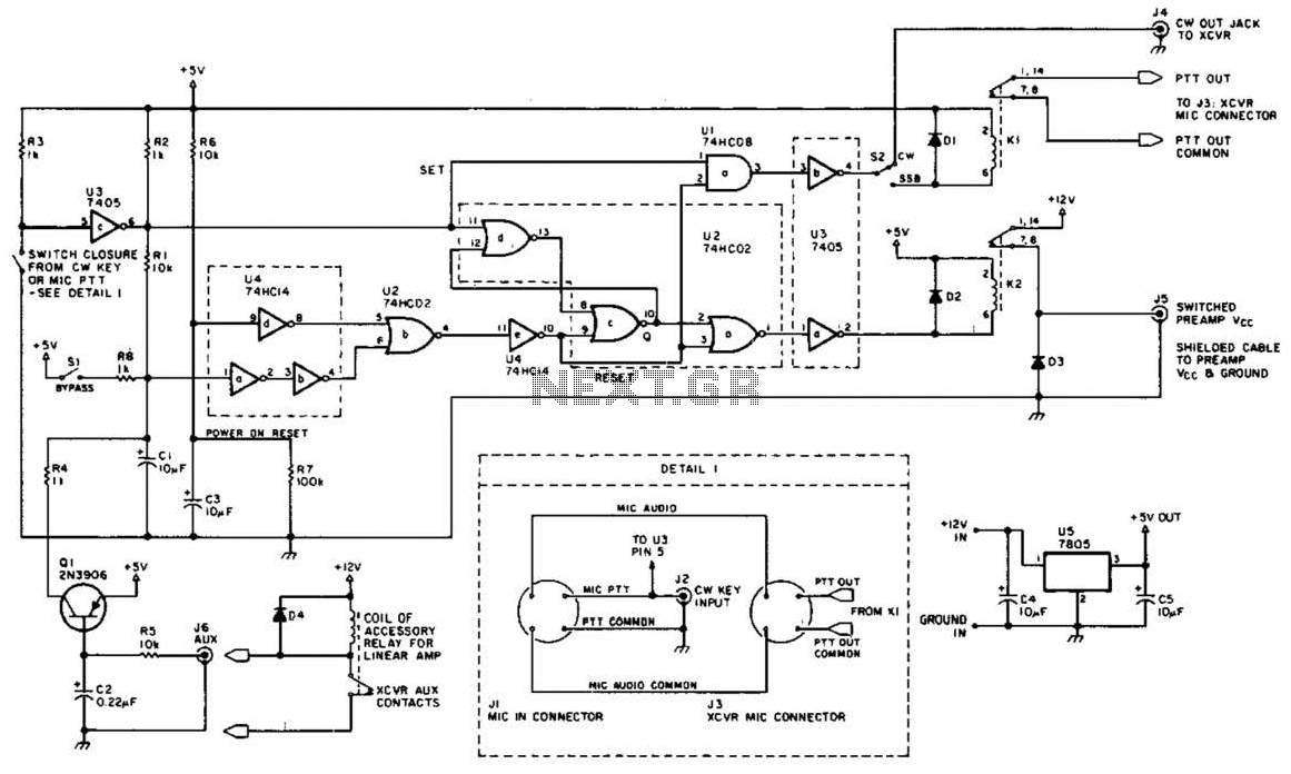
This circuit is beneficial for amateur radio operations in VHF and UHF frequencies, where a mast-mounted antenna preamplifier is employed for reception. The kit manages the transmit-receive (T-R) switching and relay sequencing to prevent high RF levels from being...
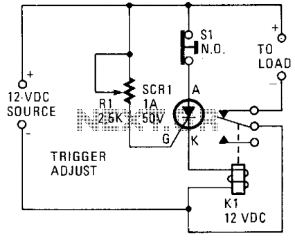
A silicon-controlled rectifier (SCR) is connected in parallel with the 12-V line and linked to a normally-closed 12-V relay, designated as K1. The gate circuit of the SCR is utilized to monitor the applied voltage. While the applied voltage...
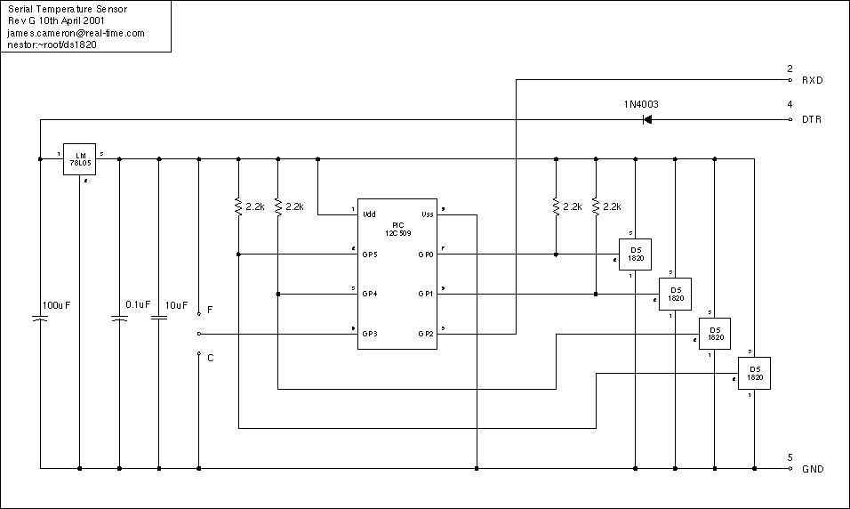
Just a handful of components builds an 8-pin microcontroller based circuit for temperature logging via a serial port; small, fast, and acceptably accurate. More: provides real-time data to your computer via serial port, interfaces up to four DS1820 temperature...
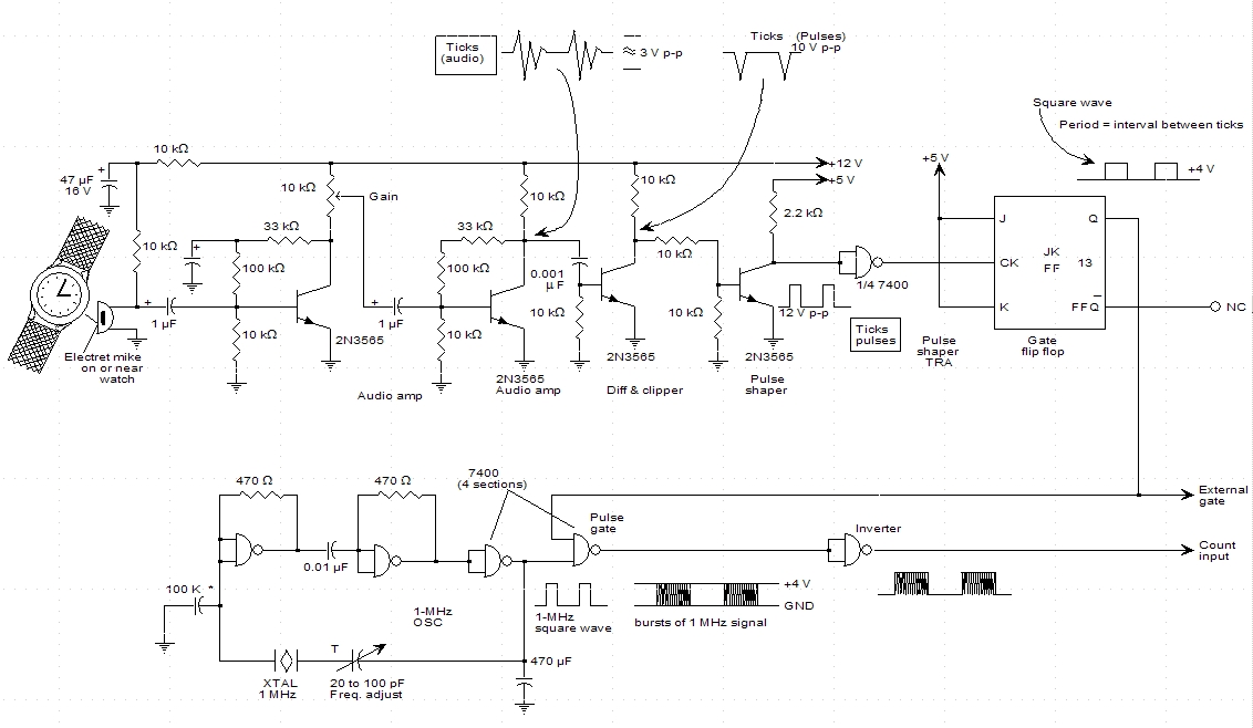
A schematic for a watch timer was found in a hobby electronics book. The circuit adapts a frequency counter to measure intervals. Watch ticks are clipped, shaped, and formed into a square wave. This square wave is utilized to...
Warning: include(partials/cookie-banner.php): Failed to open stream: Permission denied in /var/www/html/nextgr/view-circuit.php on line 713
Warning: include(): Failed opening 'partials/cookie-banner.php' for inclusion (include_path='.:/usr/share/php') in /var/www/html/nextgr/view-circuit.php on line 713