
Blinker Indicator
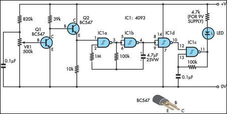
The circuit operates by utilizing two integrated circuit counters, which are pivotal in creating the sequential light pattern characteristic of turn signals. Each counter is responsible for a specific direction of the light display, ensuring that when one side is activated, the corresponding counter begins counting from zero. The reset mechanism is crucial for maintaining the display's functionality. Capacitors C4 and C7 not only serve as timing elements but also ensure that the counters are synchronized with the activation of the blinker lamp.
The NAND gate IC1 plays a vital role in managing the reset pulses for the counters. By generating a reset signal when the blinker lamp is turned off, the circuit is able to initiate a new counting cycle, allowing the display to function continuously without user intervention. The ability to adjust the progression speed of the display through potentiometer P1 provides flexibility in the circuit's operation, accommodating different preferences for visual effects.
The design also incorporates a method for brightness control through resistor R12. This feature is particularly important in automotive applications, where visibility can be affected by ambient lighting conditions. By allowing only one LED to be illuminated at a time, the circuit ensures that the brightness remains consistent and can be easily modified based on user requirements.
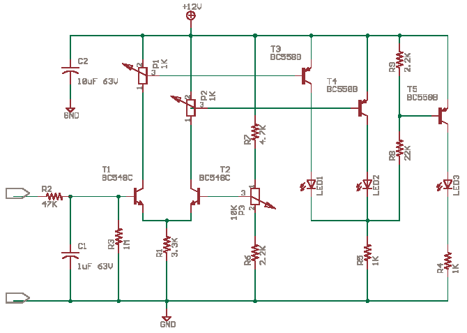
Furthermore, the option to replace standard diodes with LEDs enhances the circuit's versatility and modernizes the light display. This modification not only improves energy efficiency but also allows for a broader range of colors and brightness levels, making the blinker indicator more visually appealing. Overall, this circuit exemplifies innovative design principles in automotive lighting, combining functionality with aesthetic considerations.This circuit represents a somewhat unusual blinker indicator for use in a car or model. The running-light display progresses toward the left or the right depending on which directional signal is activated. That`s pretty cool if you`re fond of light-show effects. The circuit consists of two counters (IC2 and IC3), which are reset to zero via C4 or C7 respectively whenever a blinker lamp (La) illuminates. The running-light display thus runs through once and then stops, since the highest counter output is connected to the Enable input. When the lamp goes out, a new reset pulse is issued to the relevant counter by NAND gate IC1. A or IC1. B respectively, and the counter counts all the way up again. The progression rate of the display can be adjusted to the right speed using P1. Only one LED is on at a time (except for the hazard blinker). This allows the brightness to be easily adjusted using R12. Incidentally, the circuit can also be modified by replacing the normal diodes with LEDs, with all of the cathodes connected to ground via R12.
🔗 External reference
Related Circuits
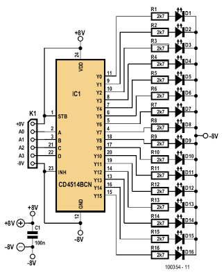
The indicator described here is specifically designed for adjusting the dynamic limiter outlined elsewhere in this edition and checking if the maximum level of the reference voltage (P1) requires modification. A 4-to-16 decoder integrated circuit (IC) of type 4514...

The circuit is powered by a 15-V wall adapter (not shown). It utilizes the characteristic of the phone line voltage, which drops from 48 V to 10 V when an extension is taken off the hook. This voltage drop...
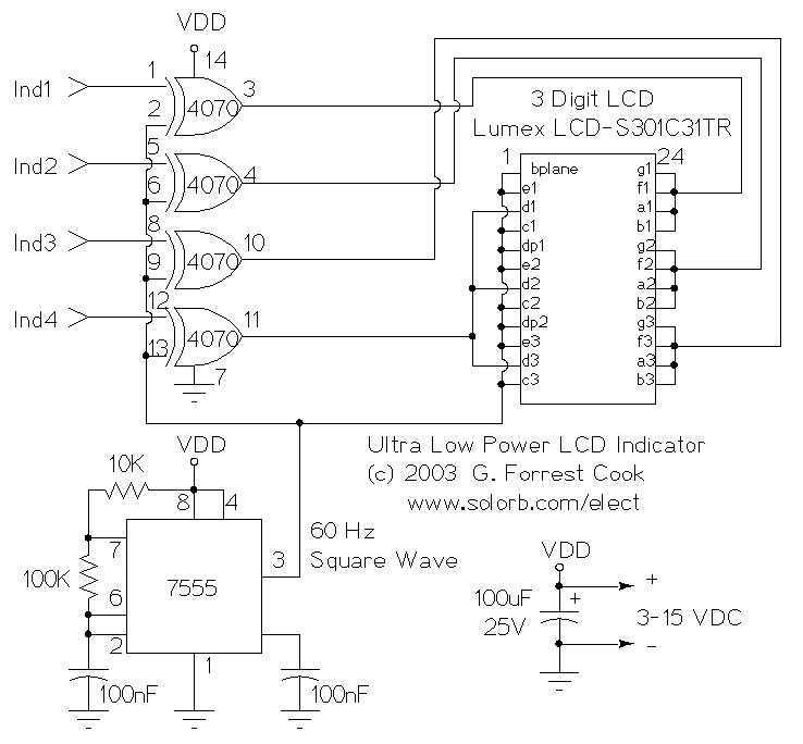
This circuit serves as an ultra-low power replacement for multiple LED on-off indicators. It also has the advantage of being easy to read in full daylight. With the parts shown, it is possible to display four bits of information....
This design integrates power-on and low-battery indication features, capable of operating with any battery voltage up to 15V. It exhibits a very low current drain of 2mA or less. The circuit design incorporates a power-on indicator that activates when the...
The circuit possesses significant educational value. It has not been tested. Users can simulate and test it or construct it to evaluate its performance. The circuit functions as a simple analog-to-digital converter. Optocouplers can be used in place of...
Utilizing an old moving coil instrument, it is straightforward to create a simple voltmeter that visually indicates the status of a telephone line. The circuit's high input impedance allows it to remain permanently connected to the line without drawing...
Warning: include(partials/cookie-banner.php): Failed to open stream: Permission denied in /var/www/html/nextgr/view-circuit.php on line 713
Warning: include(): Failed opening 'partials/cookie-banner.php' for inclusion (include_path='.:/usr/share/php') in /var/www/html/nextgr/view-circuit.php on line 713