
BMW R Series Motorcycle Regulator Schematic
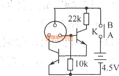
The described circuit involves a potentiometer (pot) that is used to adjust the voltage at its wiper, which is connected to a voltage source denoted as D+. The critical threshold for the operation of transistor Q1 is established by the relationship between the voltage at D+ and the voltage at the pot wiper (Vp). When the voltage at D+ exceeds certain levels, specifically when the difference (D+ - Vp) exceeds 7.6V, Q1 begins to conduct, indicating that the circuit is in an active state.
Transistor Q2 is influenced by the state of Q1 and is activated through resistor R5 when D+ falls below 13.7V. In this case, Q1 remains off, allowing Q2 to conduct, which in turn activates Q3. This cascading effect of transistors highlights a feedback mechanism that regulates the circuit's response based on the variations in D+.
The voltage across diode Df is also a significant parameter in this circuit. As D+ increases, Q1 starts to conduct, which causes a gradual decrease in the conduction of Q2 and Q3. This interaction results in a drop in the voltage across Df, indicating a dynamic adjustment in the circuit's operation based on the input voltage level at D+.
The overall design showcases a voltage regulation or control circuit that utilizes the properties of transistors and resistors to manage the flow of current and voltage levels effectively. Proper adjustment of the potentiometer is essential for ensuring that the circuit operates within the desired parameters, particularly in applications where voltage thresholds are critical for performance.Correctly adjusted, the voltage on the pot wiper is slightly less than half D+ (appx. 0.47*D+) and Q1 will conduct if (D+)-(Vp)>6.2+0.7+0.7, or 0.53*(D+) > 7.6V, (D+) > 14.3V. If D+ is lower than 13.7V, Q1 will not conduct, Q2 will get driven via R5, and Q3 will conduct. Df will carry a voltage. When D+ rises, Q1 will start conducting, Q2 will get pinched gradually, and so will Q3. Voltage on Df will drop. 🔗 External reference
Related Circuits
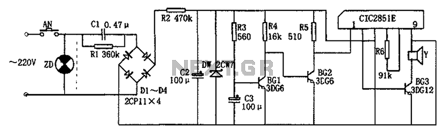
The CIC2851E refrigerator closed circuit principle involves a step-down regulator rectifier circuit, a delay circuit, a music IC (CIC2851E), speakers, and additional components. The buck regulator circuit provides a DC voltage of approximately 3V for the entire rectifier circuit....
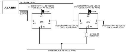
The following circuit illustrates the Ford Probe Single Wire Door Alarm System. This Single Door Locking Wire manages both LOCK and UNLOCK functions, indicating that the pulse wires must be connected to the same vehicle wire. The system primarily...
This audio limiter circuit is simple to construct and is compatible with BA741 operational amplifiers, whether in 8-pin or 4-pin configurations. It requires a symmetrical power supply. The circuit is designed to manage audio input levels effectively. The audio limiter...
Craftsman Garage Door Opener Schematic and Installation Manuals. Sears Craftsman Garage Door Opener Parts. With 15 years in the business, Garage Door Openers Superstore is a leading provider. The schematic for the Craftsman Garage Door Opener provides a comprehensive overview...
The following page outlines detailed information and the schematic of the 1985 Pontiac Fiero Wiring Diagram and Electrical System. The electrical system consists of: The 1985 Pontiac Fiero features a complex electrical system designed to support various components and functionalities...
The laser torch is an economical device with impressive cost-performance characteristics. Its primary feature is the exceptional performance of the condenser, allowing for an optical range of 1200 to 1500 meters. The beam remains focused and small even at...