
board anticipation equivalent diagram

In a case involving an anticipation rejection of a claim pertaining to an electrical circuit, the Examiner utilized a circuit diagram, asserting its equivalence to a diagram referenced in prior art. The Applicant contested this assertion, arguing the Examiner's reliance on the figure was inappropriate. The Board upheld the anticipation rejection, concluding that the Examiner's diagram was indeed equivalent and adequately disclosed the pertinent claim limitation (Ex parte Cogdill, PTAB 2010). In response, the Applicant amended the claim to further specify the two claimed impedance elements as "series" and "parallel," and introduced a "same side" limitation. The Applicant contended that Figure 3 of Johnson did not disclose the parallel impedance as claimed. The Examiner persisted with the rejection in a Final Office Action, presenting a "Figure 3b," which he described as an "equivalent circuit." The Examiner argued that the manner of drawing the schematics was inconsequential, provided the connections and nodes remained consistent, characterizing it as a matter of drawing choice.
The Examiner elaborated on the rejection, indicating that the parallel termination impedance (326) was situated between the series dampening impedance and a branch point (star node), asserting that this impedance (326) was located on the same side (below memory modules 302-308) as the driver (312). The Applicant subsequently filed an Appeal Brief, recognizing that the rejection hinged on the Examiner's "Figure 3b," purportedly an equivalent circuit. However, the Applicant's arguments focused solely on Johnson's Figure 3, asserting that it depicted a termination impedance not positioned as claimed, since it illustrated a parallel terminal impedance (326) with one end connected to a branch point and the other to the termination voltage. The claimed configuration required the parallel termination impedance to connect to a transmission line situated between the series dampening impedance and the branch point, with the parallel termination impedance located on the same side of any memory module as the driver.
In the Examiner's Answer, he reaffirmed his stance, clarifying that the rejection was based on the Figure 3b equivalent circuit rather than Figure 3 in Johnson. The Applicant then filed a Reply Brief, arguing that the Figure 3b referenced by the Examiner was not part of the Johnson disclosure and lacked the lead-in transmission line 314. The Applicant highlighted statements in Johnson regarding the advantages of the relative positioning of the series impedance and the branch point of the terminating impedance, arguing that the configuration in the Examiner's Figure 3b contradicted Johnson's objectives.
The Board ultimately agreed with the Examiner, asserting that the depiction of Johnson's Figure 3 was electrically equivalent to Johnson's description. The argument presented by the Applicant that Figure 3b was not part of Johnson's disclosure was deemed accurate but irrelevant. Figure 3b was viewed as an alternative representation of the components of Johnson's invention, electrically connected in the same manner as shown in Johnson's Figure 3. Electrical circuit diagrams serve to illustrate the interconnections between electrical and electronic components, rather than providing an exact, to-scale representation of the actual circuit layout.
In conclusion, the Applicant's failure to directly address the Examiner's findings was a critical oversight. A more effective strategy could have involved one of three approaches: challenging the legality of the Examiner introducing his own "equivalent" drawing, providing a rationale for why the Examiner's figure was not equivalent, or arguing that the equivalent circuit did not adequately teach the claimed element. The lack of a direct confrontation with the Examiner's position proved detrimental to the Applicant's case.All Things Pros covers a variety of patent prosecution topics. Here you will find prosecution strategies for handling 102, 103, 101 and 112 rejections, often discussed in the context of BPAI decisions. You`ll also find procedural topics from the MPEP such as after-final, RCE, and restriction practice. You`ll also find claim construction and infrin gement topics, in the context of BPAI, district court, or Federal Circuit decisions. Takeaway: In an anticipation rejection of a claim to an electrical circuit, the Examiner relied on a circuit diagram and asserted it to be equivalent to the diagram used in the reference. The Applicant appealed and argued that the Examiner`s reliance on this figure was improper. The Board affirmed the anticipation rejection after finding that the Examiner`s diagram was equivalent and disclosed the claim limitation at issue.
( Ex parte Cogdill, PTAB 2010. ) In response, the Applicant amended to further describe the two claimed impedance element as "series" and "parallel" and also added the "same side" limitation. The Applicant argued that Fig. 3 of Johnson did not disclose the parallel impedance as claimed. The Examiner maintained the rejection in a Final Office Action, and provided a "Fig. 3b" (shown below) which the Examiner described as an "equivalent circuit. " According to the Examiner, "it is irrelevant how these schematics are drawn as long as the connections/nodes are the same, since it is merely a matter of drawing choice.
" The Examiner then explained the rejection as follows: The parallel termination impedance (326) is between the series dampening impedance and the branch point (star node) and the parallel termination impedance (326 - where 326 is parallel in reference to Vtt and star node) is on the same side (below memory modules 302-308) as the driver (312). The Applicant appealed. In the Appeal Brief, the Applicant acknowledged that the rejection was based on the Examiner`s "Fig 3b, " allegedly an equivalent circuit.
But the Applicant`s argument addressed only Johnson`s Fig. 3. More specifically, the Applicant argued that Johnson`s Fig. 3 disclosed a termination impedance that was NOT located as claimed, since that diagram showed "a parallel terminal impedance 326 having one end coupled to a branch point, while the other end is coupled to the termination voltage" (emphasis in original). In contrast, the Applicant argued, the appealed claim required the parallel termination impedance to have "one end coupled to a transmission line between said series dampening impedance and said branch point, wherein said parallel termination impedance is on the same side of any memory module as said driver" (emphasis in original).
In the Answer, the Examiner maintained his position. He also noted that the rejection relied on the Fig. 3b equivalent circuit rather than Fig. 3 in Johnson. The Applicant filed a Reply Brief. In the Reply Brief, the Applicant argued that the Fig. 3b used by the Examiner was not part of the Johnson reference, and was also missing lead-in transmission line 314. The Applicant also pointed to statements in Johnson about an advantage of the relative position of the series impedance and the terminating impedance`s branch point.
The Applicant then argued that the configuration in the Examiner`s Fig. 3b would defeat Johnson`s objective. We agree with the Ex that this depiction of Johnson`s Fig 3 is electrically equivalent to Johnson`s description. Appellant`s argument that Fig. 3b is not part of Johnson`s disclosure may be literally accurate but is not relevant. Fig 3b is merely another way of drawing the components of Johnson`s invention, electrically connected identically to the manner shown in Johsnon Fig 3.
Electrical circuit diagrams are intended to illustrate the manner in which electrical and electronic components are connected to one another. They are not necessarily intended as an exact, to-scale representaiton of the layout of the actual circuit.
My two cents: I haven`t run across this sort of "drawing equivalence" before. I have run across plenty of cases where the Examiner has annotated a drawing, but that`s usually about further explaining what`s already in the drawing, e. g. , by adding the text "lever" to show that reference number 42 allegedly corresponds to the claimed lever.
I`ve seen a few cases where the Examiner draws a box around something in the drawing in order to explain that, e. g. , the components within the box allegedly correspond to claimed assembly 42. Maybe what happened here with the "equivalent" drawing is more like an Examiner asserting that the "lever" in the reference corresponds to the "member" in the claim.
It well-settled law that the reference doesn`t have to use the same terminology as the claim in order to anticipate. Is redrawing the circuit diagram much different than substituting the term "lever" in the reference with the word "member" That sounds weird, because Examiners don`t literally introduce paragraph [0043B] with the substituted text in order to make this point.
Instead, the Examiner writes something like In the end, the Applicant here didn`t hit the Examiner`s findings/assertions head on, and would have been better served by clearly taking one of three positions. One, argue that, as a point of law, the Examiner is not allowed to introduce his own "equivalent" drawing.
Two, explain why the Examiner`s figure was not in fact equivalent. Three, argue why the equivalent circuit did not teach the claimed element. Not hitting the Examiner`s position head on was a fatal mistake here. Perhaps the Applicant`s argument in the Reply Brief about Johnson`s objective was meant to be an argument against equivalence. If so, the Applicant should have made that more clear, because an argument about objectives of the reference may go to non-obviousness, but is irrelevant to an anticipation rejection.
🔗 External reference
Related Circuits
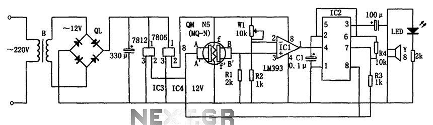
The circuit consists of a buck rectifier and voltage regulator, a gas sensor, a comparator circuit, and an alarm sound circuit. The buck regulator circuit includes a transformer, a bridge rectifier, and components such as QL, IC3 (7812), and...

As shown in FIG XTR108, a four-wire RTD is connected to the circuit. In practical applications, the lead resistance of a four-wire RTD is typically not equal, which necessitates the use of a precision operational amplifier, OPA277, to minimize...
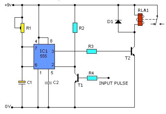
This causes T1 to conduct, pulling pin 2 of IC1 low. IC1 then enters a timing cycle, the duration of which is set by R1 and C1, resulting in pin 3 of IC1 going high. This action causes T2...
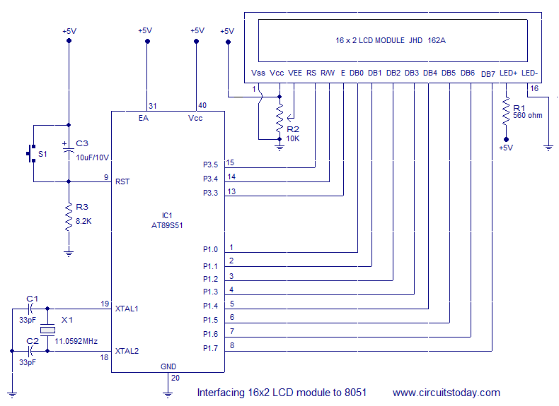
Interfacing a 16x2 alphanumeric LCD module with the AT89S51 microcontroller. The circuit diagram, theory, and program are included. JHD162 LCD module pinout and commands are provided. The integration of a 16x2 alphanumeric LCD module with the AT89S51 microcontroller involves several...
It was one of those days when learning chemistry, philosophy, and literature seemed necessary. Contemplating my plans for the day, I decided to embark on a project that I had wanted to undertake for a long time but had...
This section is designed to amplify the signal until it reaches the required level. The IF amplifier is equipped with an Automatic Gain Controller (AGC) that regulates the amplification to ensure a constant amplitude output for the video. The...