
555 pulse timer circuit diagram basic
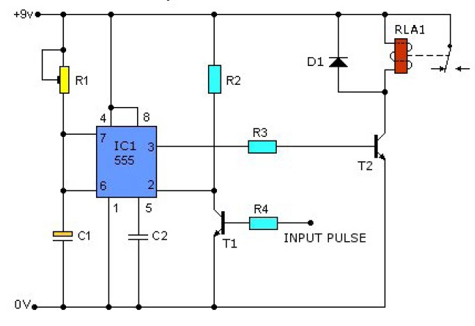
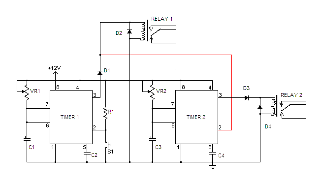
The circuit described operates using two transistors, T1 and T2, along with an integrated circuit (IC1) that functions as a timer. The operation begins when T1 is activated, which pulls the voltage at pin 2 of IC1 to a low state. This low state triggers IC1 to enter its timing cycle, the duration of which is determined by the resistor R1 and capacitor C1 connected to it. The RC time constant established by these components dictates how long pin 3 of IC1 remains high after T1 is triggered.
Once pin 3 of IC1 goes high, it activates T2, allowing current to flow through it. This action can be used to drive a load or trigger another part of the circuit. After the timing cycle concludes, T2 turns off, halting the current flow until T1 receives another pulse, thus restarting the cycle.
For component replacements, T1 can be substituted with either ECG123AP or NTE123AP transistors, ensuring that the device is rotated 180° to match the original lead configuration. Similarly, T2 can be replaced with ECG123A or NTE123A transistors, maintaining circuit integrity and functionality. The design is straightforward, making it suitable for various applications where timing and control are essential.This causes T1 to conduct, taking pin 2 of IC1 `low`. IC1 then enters a timing cycle, the duration of which is et by R1/C1, causing pin 3 of IC1 to go`high`. This causes T2 to conduct. At the end of the timing cycle T2 switches off, and the circuit waits for the next pulse toT1. T1 replacements: ECG123AP or NTE123AP (Rotate device 180 ° to conform w ith original lead configuration). T2 replacements: ECG123A or NTE123A. 🔗 External reference
Related Circuits
This key code switch circuit is an electronic circuit designed to replace conventional key switches, eliminating the need for physical key inserts. The key code switch circuit utilizes a microcontroller or a dedicated integrated circuit (IC) to interpret key codes entered...
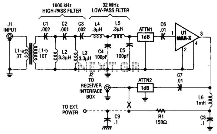
This high-frequency shortwave receiver preamplifier consists of a broadband toroidal transformer (LI-a and Ll-b), a complex LC network that includes a 1600 kHz high-pass filter and a 32 MHz low-pass filter, inductors L2 and L3 (26 turns of #26...
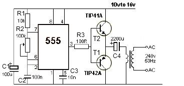
12V power inverter circuit utilizing a 555 timer for an electronic project. The 12V power inverter circuit is designed to convert a DC voltage of 12 volts into an AC voltage suitable for powering small electronic devices. The core component...
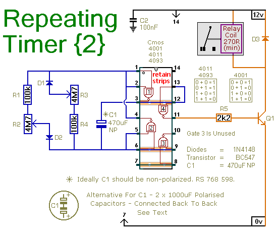
This circuit is based on a simple asymmetric oscillator. The duration for which the relay remains energized and the duration for which it remains de-energized are independently set. With the component values indicated in the diagram, both durations are...
A laser trip wire that activates a camera. An ambient light sensor from Vishay, the TEMT6000, operates as an NPN transistor connected to a 555 timer in bistable mode. The output is directed to a logic inverter for quick...
Can anyone inform me whether the output of a monostable 555 timer circuit can be utilized to trigger another similar timer circuit? I have illustrated my concept with a... The monostable 555 timer circuit is a versatile component widely used...
Warning: include(partials/cookie-banner.php): Failed to open stream: Permission denied in /var/www/html/nextgr/view-circuit.php on line 713
Warning: include(): Failed opening 'partials/cookie-banner.php' for inclusion (include_path='.:/usr/share/php') in /var/www/html/nextgr/view-circuit.php on line 713