
Video IF circuit TV Schematic Diagram

The described circuit is a Video Intermediate Frequency (IF) circuit designed for television applications. The architecture consists of several key components that work in unison to ensure high-quality video signal processing. The IF amplifier, with its AGC, plays a critical role in maintaining a stable output by adjusting gain dynamically in response to varying input signal levels. This is essential for multi-standard applications where signal characteristics may vary widely.
The PLL detector serves as a crucial element in separating the IF signal from the carrier, allowing for accurate demodulation. The phase reference generated by the PLL ensures that the demodulator can effectively retrieve the original video information from the modulated carrier. The VCO's performance is pivotal, as it must be finely calibrated to generate the correct reference frequency, ensuring optimal PLL operation.
The demodulator's ability to handle both positive and negative modulation types allows for flexibility in signal processing, accommodating various modulation schemes used in broadcasting. The IIC bus interface provides a means for digital control over the modulation selection, facilitating integration into more complex systems.
Post-demodulation, the low-pass filter is essential for cleaning up the output signal by removing high-frequency noise that could interfere with video quality. The video buffer's design is particularly focused on maintaining signal integrity, with its specified bandwidth ensuring that the full range of video frequencies is preserved while preventing distortion from noise peaks.
The inclusion of clamping circuits within the video processing path is a critical feature that helps maintain signal amplitude within defined limits, preventing distortion that can arise from signal swings exceeding typical levels. This careful design consideration is vital for producing a reliable and high-quality video output suitable for television applications.This section serves to strengthen the signal until the signal level is required. IF amplifier is equipped with AGC (Automatic Gain Controller) which controls the strengthening of the IF amplifier so that a constant amplitude output video. Amplifier frequency range from 32 ~ 60 MHz makes this amplifier suitable for applications multistandar.
IF sig nal is separated with the help of PLL detector. PLL detector produces a phase reference signal with the IF signal carrier and about 60 KHz bandwidth is determined by PLL loopfilter pin 37. Obtained by comparing the frequency demodulation reference signal with the incoming IF signal. Are required reference frequency (38. 0 MHz) generated by the VCO. Appropriate VCO frequency is determined by system calibration using the crystal as a reference. PLL can detect the IF frequency up to ± 1 MHz based on FPLL (Frequency Phase Lock Loop System) which will provide an output signal to the PLL loopfilter for the difference frequency is obtained.
If the phase IF signal with a reference signal, the signal is transmitted to the demodulator. Demodulator to control the positive and negative modulation, the selection made by the IIC bus. Low pass filter after the output signal demodulator eliminates the demodulation is not required to process the video. Video buffer to produce a video output with an amplitude of the right and keep the video output from the noise peak occurring.
The bandwidth of the video buffer at least 6 MHz. In the video there are White spot clamp buffer (for positive modulation) and the noise inverter Clamp (for negative modulation) which keeps the amplitude of the video does not exceed the typical price. You are reading the Circuits of Video IF circuit TV And this circuit permalink url it is 🔗 External reference
Related Circuits
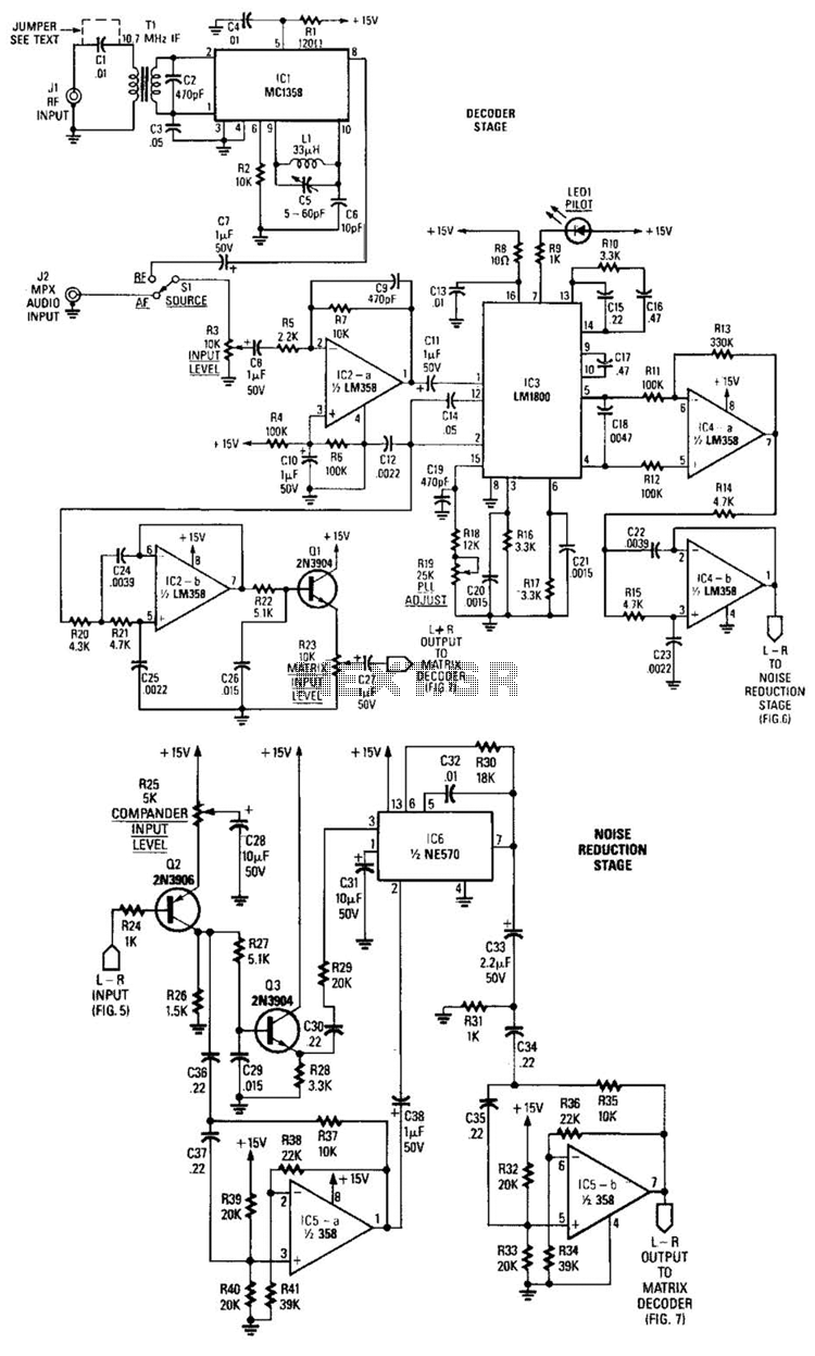
A block diagram of the stereo-TV decoder illustrates the overall relationships between the distinct sections of the circuit, while additional details of each subsection are provided. The decoder section is centered around TCI, a standard 4.5-MHz audio demodulator. The...

The remote control circuit consists of two main components: the transmitter and the receiver. A simple schematic diagram illustrates the remote control setup. The transmitter circuit utilizes a NE555 timer IC to generate a specific frequency. The receiver circuit...
Hello everyone, my name is Mike, and I come from a small country called New Zealand. I am currently planning to build a 6L6 push-pull stereo power amplifier and preamplifier. The project involves designing a 6L6 push-pull stereo power amplifier,...
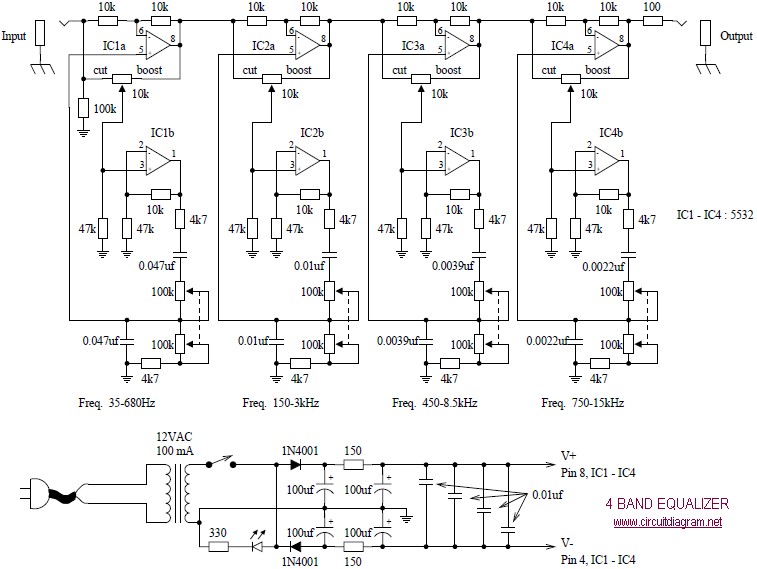
The following diagram illustrates a four-band blaster circuit. This blaster is utilized to enhance sound fidelity, emphasize specific instruments, eliminate unwanted noise, or create entirely new and distinct timbres. The four-band blaster circuit is designed to manipulate audio signals across...
This audio-video circuit enables wireless audio and visual transmission to a television. The television functions as a receiver, eliminating the necessity for a separate monitor. It can also be connected to a VCR or CCD camera, and can be...
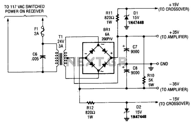
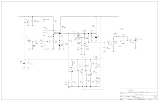
This power supply is designed to power a 100-W low-frequency amplifier and is capable of supporting various mono or stereo amplifiers within the medium power range, specifically those that require 30 to 35 V. The power supply circuit is engineered...