
Time Controlled Power-Save Mode

Modern low-power synchronous buck converters are essential components in portable electronic devices, where efficiency and battery life are critical. These converters are designed to step down voltage while maintaining high efficiency, which is particularly important in battery-operated applications. The implementation of a power-save mode enhances their operational flexibility, allowing the converters to adjust their performance based on the load conditions.
In power-save mode, the synchronous buck converter reduces its switching frequency and adjusts the on-time and off-time of the switching elements to minimize power loss. This mode is particularly beneficial during periods of low load, as it helps to maintain efficiency by decreasing the quiescent current and reducing switching losses. The converter can seamlessly transition between normal operation and power-save mode, ensuring that it meets the demands of varying load conditions without compromising performance.
Additionally, the design of these converters often includes features such as adaptive voltage positioning, which helps to optimize output voltage regulation under different load scenarios. This further enhances the efficiency and performance of the buck converter across a range of applications, from consumer electronics to industrial devices.
The integration of control algorithms within the converter's circuitry allows for real-time adjustments to the switching strategy, further improving efficiency. The ability to maintain high efficiency over the entire load range is critical for extending battery life in portable applications, making modern synchronous buck converters a vital component in the design of energy-efficient electronic systems.More Flexibility For Low-Power Synchronous Buck Converters Modern synchronous buck converters for portable applications provide so called power-save mode operation to maintain high efficiency over the entire.. 🔗 External reference
Related Circuits
Considering the rapid advancements in the electronics industry, the 555 timer could be regarded as a constant in an ever-evolving landscape. What exactly is the 555 timer? How does it function? In what ways can it be utilized? And...
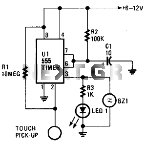
The circuit is based on a 555 oscillator (U1), which activates when a trigger is applied by touching the touch terminal connected to pin 2 of U1. Once triggered, LED1 and BZ1 (a piezoelectric buzzer) illuminate for a duration...

This is a simple hobby circuit for a remote-controlled toy car. The primary component utilized is the IR sensor circuit, which includes a TSOP IR receiver. This receiver allows the user to start and stop the DC motor of...
This circuit deactivates an amplifier or other devices when a low-level audio signal at its input is absent for at least 15 minutes. By pressing P1, the device is activated, supplying power to any appliance connected to SK1. The...
Input values for R1, R2, and C, then press the calculate button to determine the positive time interval (T1) and negative time interval (T2). For instance, using a 10K resistor (R1) and a 100K resistor (R2) along with a...
The choice of material to read or drive is the definition of three digits (Bit), RA0, 1,2 PORTA of the PIC at the entrance of 74HC138A. To select a material for reading or driving an output of 78HC138 is...