
presence circuit

The intelligent presence simulator circuit is designed to enhance home security by simulating occupancy. The core of the system is the Microchip PIC12C508 microcontroller, which is programmed to randomly turn lights on and off in response to changing ambient light conditions. This randomness is key to creating a believable presence, as it prevents predictable patterns that could be easily observed by potential intruders.
The circuit is powered by the mains supply, ensuring that it remains operational without the need for battery replacements. A zener diode is employed for basic voltage regulation, providing a stable power supply to the microcontroller and ensuring consistent performance. The use of a relay to control the lights offers a robust solution, as it isolates the microcontroller from the high voltages of the mains, thereby reducing the risk of damage during power surges or storms.
The light-dependent resistor (LDR) serves as the ambient light sensor, detecting when the light levels drop below a certain threshold. This threshold can be adjusted using a potentiometer (P1), allowing for customization based on the specific environment and placement of the LDR. This adjustability ensures that the simulator can effectively respond to varying lighting conditions throughout the day and night.
In summary, this intelligent presence simulator circuit provides an effective means of deterring burglary by creating the illusion of occupancy through irregular lighting patterns. Its simplicity, reliability, and adaptability make it a practical solution for enhancing home security.However effective a domestic alarm system may be, it`s invariably better if it never goes off, and the best way to ensure this is to make potential burglars think the premises are occupied. Indeed, unless you own old masters or objects of great value likely to attract professional` burglars, it has to be acknowledged that the majority of burglarie
s are committed by petty` thieves who are going to be looking more than anything else for simplicity and will prefer to break into homes whose occupants are away. Rather than simply not going on holiday which is also one solution to the problem (!) we`re going to suggest building this intelligent presence simulator which ought to put potential burglars off, even if your home is subjected to close scrutiny.
Like all its counterparts, the proposed circuit turns one or more lights on and off when the ambient light falls, but while many devices are content to generate fixed timings, this one works using randomly variable durations. So while other devices are very soon caught out simply by daily observation (often from a car) because of their too-perfect regularity, this one is much more credible due to the fact that its operating times are irregular.
The circuit is very simple, as we have employed a microcontroller a little` 12C508 from Microchip, which is more than adequate for such an application. It is mains powered and uses rudimentary voltage regulation by a zener diode. A relay is used to control the light(s) though this is less elegant than a triac solution, it does avoid any interference from the mains reaching the microcontroller, for example, during thunderstorms.
We mustn`t forget this project needs to work very reliably during our absence, whatever happens. The ambient light level is measured by a conventional LDR ( light dependent resistor), and the lighting switching threshold is adjustable via P1 to suit the characteristics and positioning of the LDR. 🔗 External reference
Related Circuits
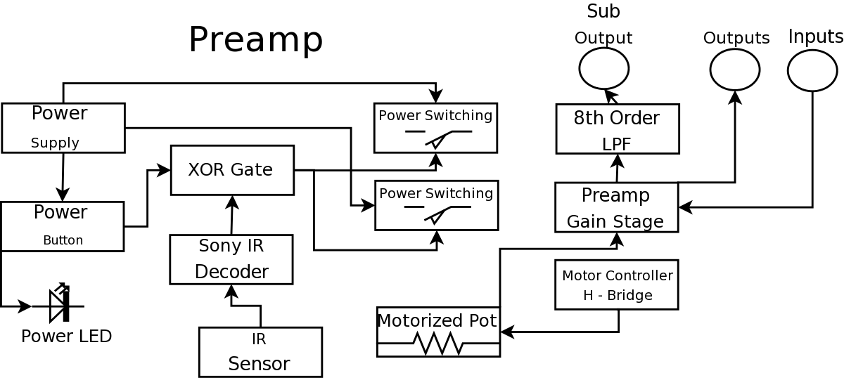
During a Digital Projects Lab, the professor suggested incorporating more circuit-level work into a project. To achieve this, a preamplifier was designed, which included an infrared (IR) remote control to replace a previously built version. The earlier preamplifier functioned...
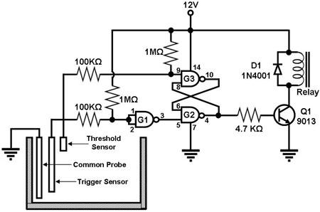
Figure 1 illustrates a circuit designed to monitor the water level in a tank and control a water pump accordingly. The primary component of the circuit is the CD-4011 Quad NAND gate, with three of its gates utilized as...
The alcohol detection alarm controller circuit is illustrated in the figure. It utilizes the QM-NJ9 alcohol gas sensor, which detects the presence of alcohol vapors. When alcohol is detected, the resistance between the AB-QM-NJ9 decreases, causing the wiper of...

This document describes a 100 Watt inverter circuit that utilizes a minimal number of components. The circuit employs the CD 4047 integrated circuit (IC) from Texas Instruments to generate 100 Hz pulses, along with four 2N3055 transistors that drive...

Cellular phone detector circuit schematic using common electronic parts The cellular phone detector circuit is designed to identify the presence of a cellular phone within a specified range. This circuit utilizes basic electronic components, making it accessible for hobbyists and...

This simple circuit illustrated in the schematic diagram activates the switch using sound. It can be utilized for various applications, such as automatic (sound-controlled) disco lights or car LED light shows. The transistor Q1 amplifies the audio from the...
Warning: include(partials/cookie-banner.php): Failed to open stream: Permission denied in /var/www/html/nextgr/view-circuit.php on line 713
Warning: include(): Failed opening 'partials/cookie-banner.php' for inclusion (include_path='.:/usr/share/php') in /var/www/html/nextgr/view-circuit.php on line 713