
Bots Circuit Designs
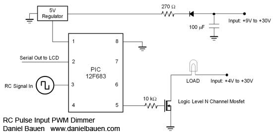
The circuit design utilizing the PIC12F675 or PIC12F683 microcontroller focuses on creating a versatile control system that can manage various loads through PWM. The microcontroller's ability to interpret short pulse widths from a remote control enables it to effectively switch outputs based on user input. The configuration can be adjusted to accommodate different numbers of outputs, depending on application needs.
In a typical setup, the microcontroller receives a pulse width signal from the remote control, which is processed to determine the desired output state. The rotary knob on the remote allows for smooth transitions between different output relays, providing an intuitive user interface. This is particularly advantageous in applications such as model aircraft, where precise control over motor speed or light intensity is required.
The implementation of PWM through the PIC12F683's HPWM feature allows for efficient management of power to the load. This is crucial in applications where energy conservation and heat management are important. The HPWM channel operates independently of the main program execution, enabling the microcontroller to perform other tasks without interrupting the PWM signal.
For a practical application, the circuit can be designed to control a DC motor, where the PWM signal adjusts the average voltage supplied to the motor, thus controlling its speed. Similarly, for lighting applications, the PWM can modulate the brightness of LED lights by varying the duty cycle of the signal, leading to a range of brightness levels without the need for bulky resistive dimmers.
Overall, this circuit exemplifies the integration of microcontroller technology with remote control systems, providing a flexible solution for various electronic control applications. The ability to customize the circuit for different outputs and loads makes it an ideal choice for hobbyists and engineers alike.Using a PIC12F675, up to 5 outputs can be switched sequentially using a standard Remote Control pulse input of between 1 to 2 ms. Although any RC channel input can be used, it is especially useful when used with the rotary knob channels (usually 5 and above on RC airplane remote).
The knob can be rotated to a certain position, selecting which outp ut relay will be turned on. The example circuit shown below switches between 3 inputs to 1 output. Many different configurations could be created for specific applications. A larger PIC could be used for more switching outputs. This is a useful circuit for Pulse Width Modulation of a load using a standard Remote Control pulse input of between 1 to 2 ms. The circuit can be used as a simple motor speed controller, or to control the brightness of a light, or other loads that need a variable voltage.
The PIC12F683 is ideal for this purpose, because it is a small microcontroller, that has a hardware pulse width modulation channel (HPWM). This means that the PWM signal runs in the background while the microcontroller processes the rest of the code.
So the PWM output is not dependent on the length of time it takes to execute a program loop. 🔗 External reference
Related Circuits
Firecrackers are typically ignited using a matchstick or candle. After igniting the fuse, it is necessary to retreat quickly to a safe distance. This method poses safety risks due to the possibility of the firecracker detonating before reaching a...
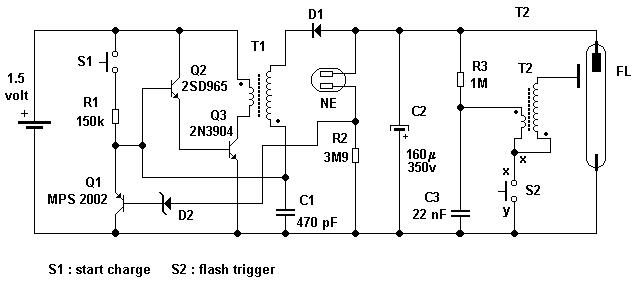
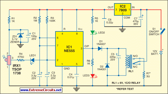
A simple transistor generator and transformer converts a 1.5V battery voltage to several hundred volts. This high voltage current then passes through a diode, which rectifies the current to DC. This DC current is stored in a relatively large...
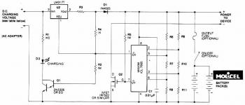
This circuit illustrates a Lithium Battery Charger circuit diagram. Charging is achieved using a constant current of 60 mA for AA cells until a cutoff voltage of 2.4V per cell is reached, at which point the charging process must...
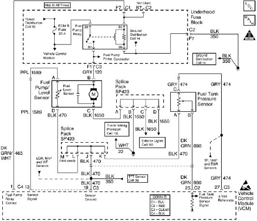
The control module monitors the fuel tank pressure (FTP) sensor signal to detect vacuum decay and excess vacuum during the enhanced evaporative emission (EVAP) diagnostic. The Fuel Tank Pressure Sensor responds to changes in the fuel tank pressure or...
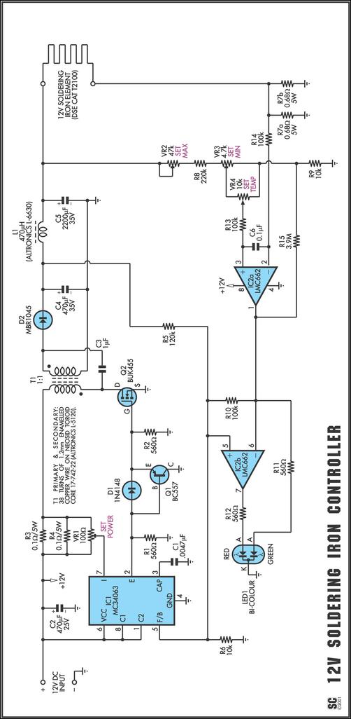
One reason commercial soldering stations are costly is that they typically require soldering irons with built-in temperature sensors, such as thermocouples. This circuit removes the necessity for a specialized sensor by detecting the temperature of a soldering iron heating...
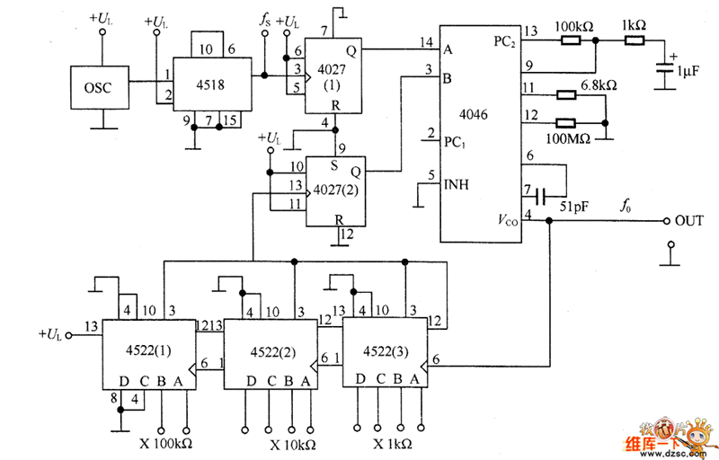
The PLL synthesizer oscillator circuit is a feedback loop consisting of a reference oscillator, phase comparator, loop filter, voltage-controlled oscillator, programmable frequency divider, and various other components. In this circuit, the reference oscillator employs a crystal oscillator (OSC) to...