
Infrared Fire-Cracker Igniter circuit
The circuit design incorporates several essential components to ensure safe and effective operation. The IR receiver module TSOP1738 is sensitive to infrared signals, allowing it to receive commands from a standard remote control. The output from this module is processed by IC1, which is configured in a monostable mode. This configuration ensures that a single pulse is generated when the remote is activated, allowing for precise control over the ignition timing.
The relay RL1 acts as a switch that controls the high-power circuit connected to the heater element R7. When IC1 is triggered, it energizes the relay, allowing the current to flow through R7. The use of a heater element as the ignition source is critical; it is designed to reach high temperatures quickly, ensuring reliable ignition of the firecracker. The thermal inertia of R7 ensures that it can withstand the brief but intense current without damage.
The circuit's power supply is a 12V, 7AH battery, which provides sufficient current for both the control circuit and the ignition system. IC2 steps down the voltage to approximately 9V, which is suitable for powering the logic components without risking damage from higher voltages.
Safety considerations are paramount in this design. The metallic cabinet serves to contain any accidental ignition events, and the careful routing of wires ensures that they do not come into contact with heated components. Additionally, the circuit's design should incorporate fuses or circuit breakers to protect against overcurrent conditions, further enhancing safety during operation.
Overall, this remote-controlled firecracker ignition system provides a safer alternative to traditional ignition methods, allowing users to ignite firecrackers from a distance while minimizing the risk of injury.Firecrackers are normally ignited by using a matchstick or a candle. You have to run away quickly after igniting the fuse of the firecracker. This method of igniting firecracker is unsafe, because the danger of the firecracker bursting before you reach a safe distance is always there. The device described here uses remote control, usually used wit h TV receivers or CD players, to burst the fire-cracker. Thus the firecracker can be ignited from a safe distance using the circuit described below in conjunction with the remote control. In the diagram shown here, normally the output of IC1 is low and green LED2 is on` and the red LED3 off.
` This indicates that the circuit is ready for use. When any key on the remote control is pressed, output pin 3 of IRX1 (IR receiver module TSOP1738) goes low. This output is connected to pin 2 of IC1 via LED1 and resistor R4 to trigger the monostable operation of IC1.
The output of IC1 remains high for a period equal to 1. 1G—R2G—C2. With the values of the components given in the circuit diagram here, the period works out to 3. 5 seconds approximately. This activates relay RL1 and red LED3 glows and green LED2 turns off. On` state of red LED3 indicates that the firecracker is about to burst. R7 is a small part of the element of an electric heater (220V, 1000W), which is kept away from the electronic circuit and connected to the relay contacts through a thick electric cable. The resistance value of short length of the heater element (R7) is 3 to 3. 5 ohms. A current of around 4 amperes flows through it when connected to a 12V battery. Flow of 4A current through R7 for 3. 5 seconds makes it red hot, which ignites the fire-cracker. The circuit is powered by a 12V, 7AH battery. IC2 provides about 9V for the operation of the circuit. The circuit should be housed in a metallic cabinet to prevent it from being damaged by bursting of the firecracker.
The IR receiver and the two LEDs should be fixed on the front panel of the cabinet. Wiring and relay used in the circuit should be chosen such that they are able to carry more than 5 amperes of current. 🔗 External reference
Related Circuits
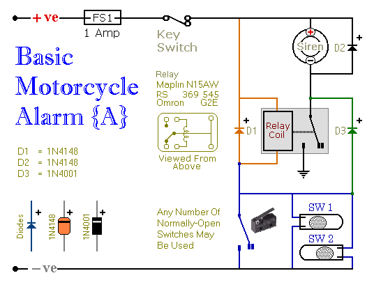
Relays can be utilized to protect motorcycles and have various other applications. When using relays with 6-volt coils, they provide security for "Classic Bikes." The alarms are compact, with completed boards occupying approximately half a cubic inch (8 cc)....
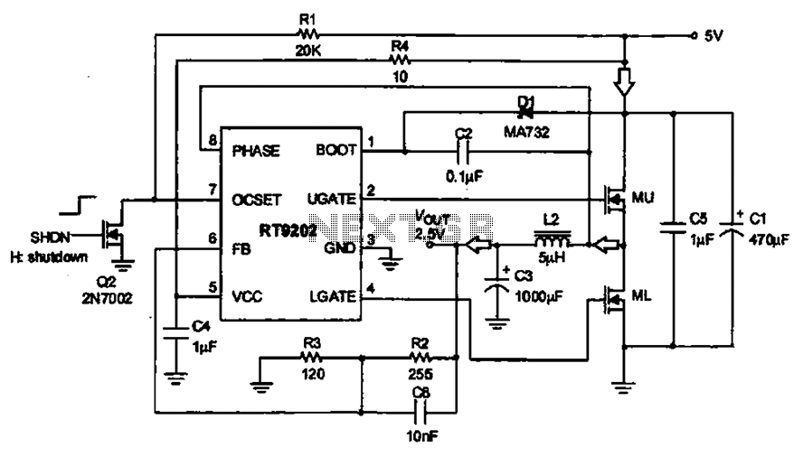
A 5V to 2.5V voltage regulator circuit is designed for use in computer motherboards. At its core, this circuit utilizes the RT9202 power management chip. The RT9202 functions as a switching pulse generating circuit, which, upon startup, converts a...
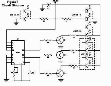
It consists of a 4047 low-power monostable/astable multivibrator, IC1, used in the astable mode to provide the timing pulses to control the flash rate of the LEDs. To accomplish the astable mode, pins 4, 5, 6, and 14 are...

An ultra-low-noise, low-distortion operational amplifier, the AD797, is combined with the ADS 11 operational amplifier, which provides high bandwidth and a 100-mA output drive capability. This composite amplifier circuit is effective for driving high-resolution ADCs and ATE systems. The...
This add-on circuit enables remote switching on and off of battery-operated toy cars using a TV or video remote control handset that operates at 30 to 40 kHz. When powered by a 6V battery, the decade counter CD4017 (IC2),...
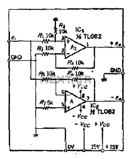
A balanced output is often associated with the positive phase amplifier output terminal of an operational amplifier, which is typically viewed as the inverting amplifier circuit. However, the reversed phase output can lead to a loss of balance in...