
Brain Wave Machine

The construction of a brain-wave machine involves a straightforward assembly process that integrates both hardware and software components. The goggles, which serve as the primary interface for visual stimulation, are crafted from safety glasses that provide a secure fit while allowing for the placement of LEDs. The arrangement of the LEDs in a diamond pattern on each lens not only enhances the visual experience but also ensures that the light is effectively directed towards the user's eyes, facilitating the desired brain-wave entrainment.
The use of a parallel port for controlling the LEDs is a practical choice, as it allows for precise timing and synchronization of the light pulses. Each LED is connected to a specific data output pin on the parallel port, enabling independent control over the flash rates and patterns. This feature is crucial for achieving varying stimulation effects, which can be tailored to the user's preferences or specific brain-wave states sought.
In addition to the visual component, audio stimulation is integrated into the system, utilizing either a stereo system with headphones or the sound card of the PC. This dual-modality approach—combining auditory and visual stimuli—enhances the overall efficacy of the brain-wave machine, as both senses work together to induce the desired mental states.
When constructing the device, careful attention must be paid to the wiring and connections to ensure reliability and safety. The use of long wires allows the user to maintain comfort during sessions, as they can lie down while using the goggles. Proper strain relief is also essential to prevent any accidental disconnections or damage to the components during use.
Overall, this DIY brain-wave machine presents an accessible option for individuals interested in exploring brainwave entrainment techniques without the need for expensive commercial devices. By following the outlined steps and ensuring careful assembly, users can create an effective tool for enhancing mental states and promoting relaxation and creativity.By using light and sound to induce these brain states we are able to gain greater control and efficiency of brain usage. Furthermore, improvements in relaxation, memory, creativity, stress management, sleep disorders, and even ESP(!) can be had by utilizing a brain-wave machine.
Commercial brain-wave machines cost hundreds of dollars, but you can build your own using only a few dollars worth of components. In this document I will walk you through hardware construction and softw1are control of an easy to build brain-wave machine. Disclaimer: I am not an electronics expert or a biofeedback specialist. If you fry your hardware (or your wetw1are) don`t come whining (or drooling) to me. I assume no responsibility for what you do with this information. With simplicity being the goal, brain-wave goggles can be constructed from suitable eyewear, such as safety glasses, and an array of LED`s (Light Emitting Diodes).
I`m using the PC`s parallel port to control the flashrate of the LED`s. Audio stimulation can be provided by a stereo and headphones or the PC`s soundcard. I`m using 8 LED`s, one per parallel port data out line. This provides an easy way to control each individual LED allowing for some variations in pattern and intensity. Each lense on the goggles will hold four LED`s in a diamond pattern. The LED`s are powered by the parallel port and controlled via softw1are. 8 LED`s (choose green, yellow, or red LED`s) DB25 pin male parallel port connector (or butcher a printer cable) Goggles (safety glasses or similar eyewear) Wire Glue the LED`s into the holes.
Be sure there is room betw1een the LED`s and your face when you are wearing the goggles. Actually, the LED`s fit tightly in 3/16" holes and I didn`t need to use glue. Wire all of the LED`s cathode leads together and connect (with a long wire) to a ground pin on the parallel port connector. Pins 18-25 are all ground so pick any one of those. Note: the flat side of the LED is the cathode lead. Connect the LED`s anode leads to the parallel port connector. Follow the circuit diagram above which outlines which parallel port pin to connect each LED to. Use long wires, you are going to want to be lying down when you use the goggles. (If you are using a printer cable you can use a battery and a LED to figure out which pin each wire is attached to.
) If your parallel port wires aren`t already in a bundle tie them together with wire-ties so they don`t get tangled. You will also want to provide strain-relief by attaching the wire bundle to the goggles so it doesn`t get pulled off.
🔗 External reference
Related Circuits

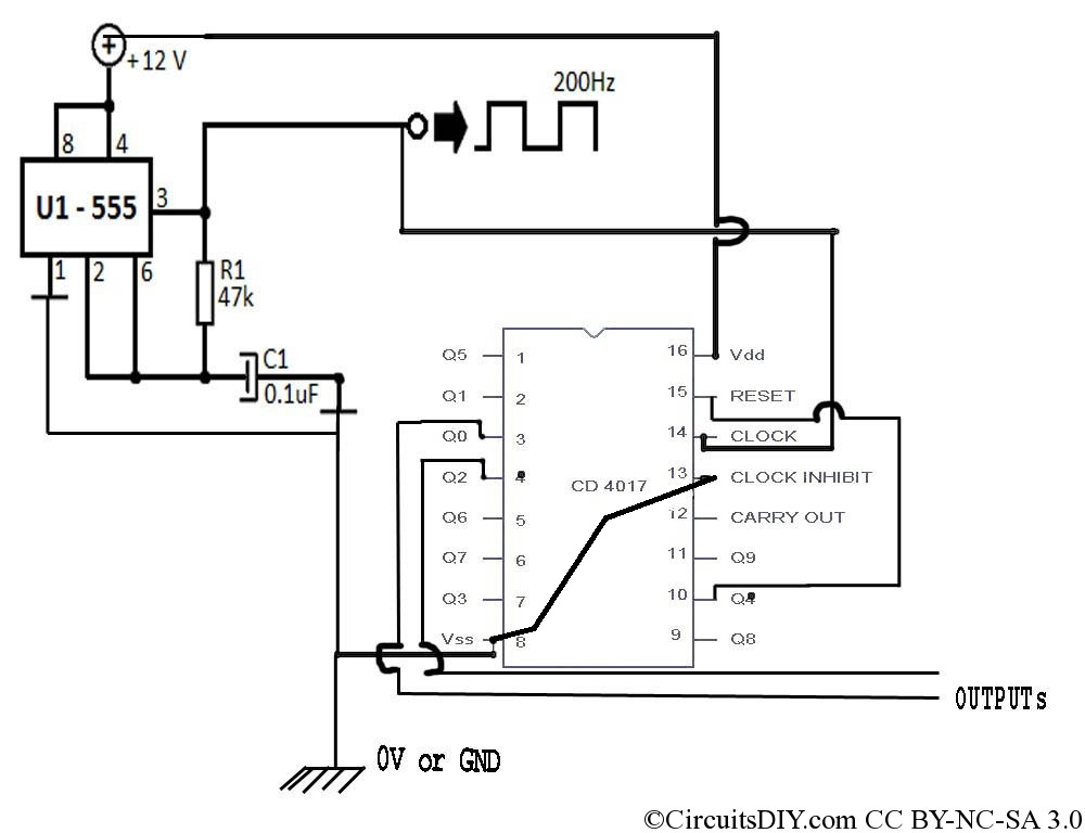
Generating sine waves with controlled frequencies over a wide range is challenging when using RC or LC sinusoidal oscillators. However, this can be effectively achieved using a wideband digital square wave oscillator, a counter, and a weighted summing network....
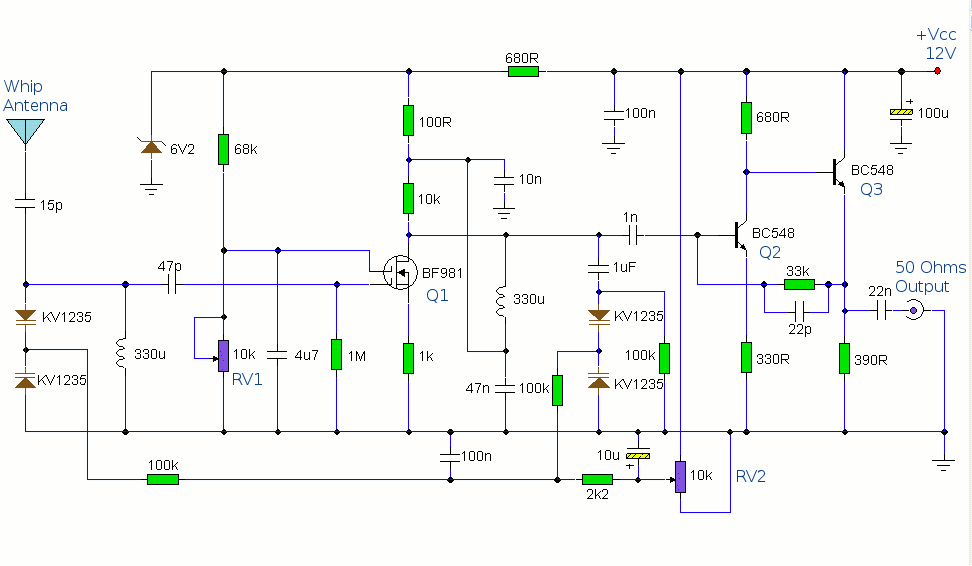
This circuit is designed to amplify the input from a telescopic whip antenna. The preamplifier is designed to cover the medium waveband from about 550KHz to 1650KHz. The tuning voltage is supplied via RV2, a 10k potentiometer connected to...
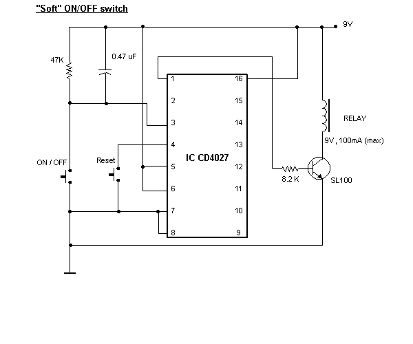
Most inverters available in the market utilize a modified sine wave to achieve better output at a competitive cost. The modified sine wave unit employs a 50% fixed PWM square wave, with the peaks balanced by a capacitor to...
Many applications require low-frequency signal generators that can deliver high-performance, high-resolution signals. This design idea presents a circuit that generates frequencies from 0 to 1 MHz, providing sinusoidal, triangular, and square-wave outputs with frequency resolution better than 0. A...
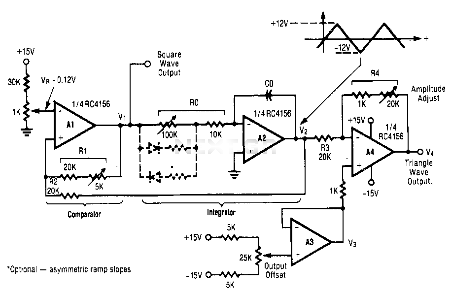
This circuit utilizes a positive-feedback loop that encompasses a combined comparator and integrator. Upon the application of power, the output of the comparator transitions to one of two states, either the maximum positive or maximum negative voltage. This action...
A 555 timer operating in astable mode generates driving pulses, while two 4518 dual BCD (binary coded decimal) counters provide square waves. A TL081 operational amplifier functions as an output buffer-amplifier. Potentiometers R1 and R2 are utilized to control...