
Strobe Light circuit

The stroboscope circuit primarily relies on the functionality of the NE555 timer ICs, which are versatile components commonly used in timing and pulse generation applications. The astable configuration of IC1 allows for continuous oscillation, generating a square wave output that can be fine-tuned via the variable resistor VR1. This variability enables the user to select a frequency that aligns with the speed of the observed object, thereby creating the desired stroboscopic effect.
The coupling capacitor (C6) serves to isolate the two stages of the circuit while allowing the AC signal from IC1 to pass through to IC2. In the monostable configuration of IC2, the pulse width is determined by the resistance of VR2 and the capacitance of the timing capacitor associated with this IC. This capability to adjust pulse width is crucial for achieving optimal synchronization between the strobe light and the moving object.
Transistor T1 functions as a switch, amplifying the signal from IC2 to drive the transformer, which is essential for stepping up the voltage to power the tube light. The transformer X1, designed for step-up operation, converts the low voltage from the transistor output to a higher voltage suitable for the tube light, ensuring adequate illumination for effective observation.
Overall, the stroboscope circuit is designed to provide a reliable and adjustable means of visualizing rapid motion, making it an invaluable tool in various applications, including mechanical fault detection and motion analysis. The careful selection and configuration of components ensure that the strobe light can be finely tuned to match the dynamics of the observed object, achieving the effect of apparent stillness.A stroboscope is an instrument which is used to view the object which is moving rapidly with a periodic motion as if they are at rest. The strobe light flashes at a frequency that synchronizes with the resolution of a wheel or moving object which seems to be at a still position.
The circuit of strobe light utilize neon lamp because their light is dim to detect the fault, for good illumination a 9 inch tube-light is used. The circuit of strobe light is wired easily available timer IC NE555 (IC1, and IC2). IC1 is wired as astable multivibrator whose frequency can be varied over 1:10 range through variable resistor VR1. Rotary switch SW1 is used to select the range with proper adjustment this astable mode can be generate 1.
2 Hz to 12 KHz frequency. The output of IC1 from pin 3 is given to pin 2 of IC2 through coupling capacitor C6. The IC2 is wired as monostable multivibrator whose output pulse width can be varied from 100 µs to 100 ms with the help VR2. Rotary switch SW2 is used to select the range. The output of IC2 from pin 3 is given to base of transistor T1 through current resistor R5. The output of transistor is connected to secondary transformer. The transformer X1 (6V-0V secondary) is used in reverse mode (i. e. step up mode). The 6V terminal is connected to 12V DC supply and 0V to output of transistor as shown in circuit diagram of strobe light (figure 1).
Oscillating current are generated in 6 volts winding as per our adjustment and stepped up to light the tube light. The tube-light is focused on tatting table fan blade and the frequency and pulse width is adjusted so that both are synchronized.
This happens when the fan blades seem to be stand-still. 🔗 External reference
Related Circuits
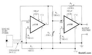
The following circuit illustrates a fully linear diode sensor circuit diagram. This circuit is based on the A748 integrated circuit (IC). Features include the use of an operational amplifier (op-amp). The fully linear diode sensor circuit utilizes the A748 IC...
The system is managed by the master controller LKl-12/90 and a magnetic disk control unit PQR10A, which includes a control circuit. The cam control device SA is responsible for contact closure, as indicated in Table 8-5. The main electrical...

Both circuits can synchronize trapezoidal wave voltage, which is converted into intermittent small rectangular pulses. Its working principle involves periodic operation in synchronization with the grid frequency of the zero-volt switching voltage of the DC chopper. Due to the...

This project involves the construction of a VHF-UHF linear amplifier capable of operating at frequencies ranging from 47 MHz to 740 MHz. It serves as the final output stage for any transmitter functioning within these frequencies. The amplifier utilizes...
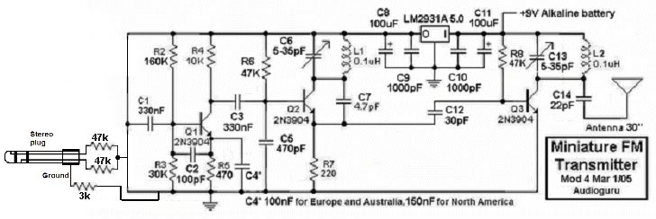
This small FM transmitter can be modified to replace the microphone with an audio jack, allowing it to connect to an MP3 player for audio playback through car audio systems. The design is straightforward and intended for a short...

This circuit diagram represents a lamp flasher powered by mains electricity. It is capable of flashing lamps with a maximum power of 200 Watts at user-defined rates. The NE555 integrated circuit is configured as an astable multivibrator, generating the...