
Breadboard header for ATTiny

The described breadboard header serves as an efficient interface for the ATTiny 25/45/85 microcontroller, facilitating easy integration into prototyping environments. The board's design allows for power distribution to vertical breadboard strips, ensuring that the microcontroller and peripheral components receive the necessary voltage and current.
Key components include a 6-pin In-System Programming (ISP) connector, which is compatible with the USBtinyISP programmer, allowing for straightforward programming and debugging of the microcontroller. The reset button is conveniently placed for quick access, enabling users to reset the microcontroller without needing to manipulate the breadboard setup.
The board features a header for an optional ceramic resonator, which can be used to stabilize the microcontroller's clock signal, improving timing accuracy in applications. A green LED indicator is included to provide visual feedback on power status, enhancing usability during development.
Capacitance is managed by two capacitors: a 100nF capacitor (C1) for decoupling and a 100uF/16V capacitor (C2) for smoothing out voltage fluctuations, which is crucial for maintaining stable operation of the microcontroller and connected devices.
The board is designed to accommodate various header configurations, including 1x2, 1x3, 1x6, and 2x3 arrangements, enhancing flexibility for connecting additional components or modules. An 8-pin IC socket is provided for the ATTiny microcontroller, allowing for easy replacement and ensuring that the microcontroller can be securely mounted.
It is essential to solder the wire link beneath the IC socket as indicated (red line) to ensure proper connectivity and functionality of the board. This design consideration is crucial for maintaining the integrity of the circuit and ensuring reliable operation during prototyping and testing.This handy breadboard header for ATTiny 25/45/85 microcontroller is a new design based on the original idea from Tinkerlog. Maybe the most useful feature is that it can provide power to the vertical breadboard strips while connecting all six port pins to the horizontal strips.
Other features are :6-pin ISP connector (works great with USBtinyISP programmer). easily accessible reset button. header for optional ceramic resonator. power led indicator. smoothing caps. Measuring approx. 4 x 2.5 cm (1½ x 1 in) is a great addition to your breadboard projects saving lots of extra connections. R1 10k? R2 330? C1 100nF C2 100uF/16V LED1 Green 3 mm Button Omron type button Headers 1x2, 1x3, 1x6, 2x3 IC Socket 8 pin MCU ATTiny 25/45/85 PDIP Don?t forget to solder the wire link under the IC socket (red line) ! 🔗 External reference
Related Circuits
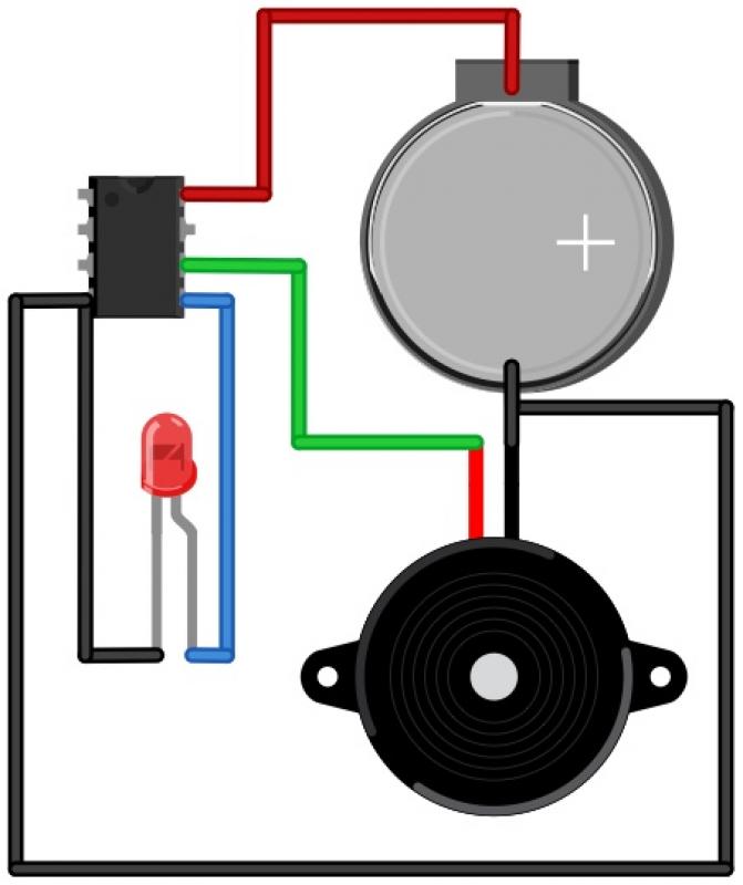
The Morse Beepy is a circuit designed to be simple and affordable, making it suitable for both children and adults as an introductory soldering project. It can be assembled and programmed within fifteen minutes to beep and blink a...
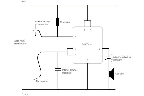
Ensure to verify all connections utilizing the circuit diagram and breadboard schematic available for download from the provided links. This resource can assist during the assembly process. To create a reliable electronic circuit, it is essential to meticulously verify all...
The device described here does just that. The circuit connects to the doorbell circuit, taking power from the 18 VAC from the doorbell transformer and switching power to the doorbell circuit most of the day. The user interface is...
This firmware is intended to run on an Atmel ATtiny2313 operating from a 4, 8, 10, 16, or 20 MHz clock or an AT90S2313 operating from a 4 MHz clock. As far as I have been able to determine,...
Plug an ATtiny12 into the 8 pin socket and hold down "GO!" button. The LED will come on at the end of the programming process, which only takes a couple hundred milliseconds. The fuses are now restored to their...
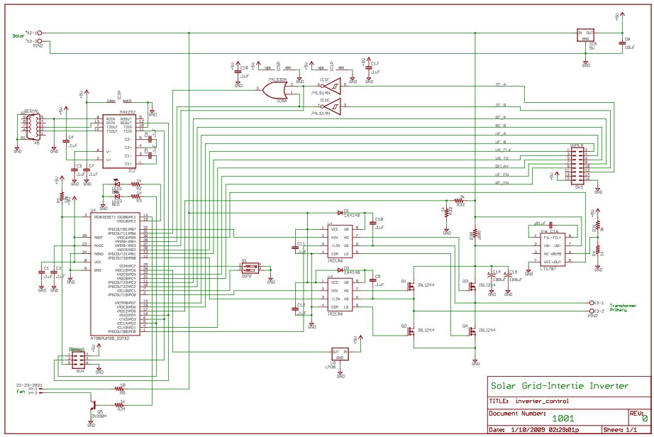
For the last year, a prototype for a solar inverter that can be grid-intertied has been developed. A solar inverter converts 12V DC (or other voltages) from solar panels. The solar inverter is a crucial component in photovoltaic systems, responsible...