
Build Your Own 555 Timer
The 555 timer is a popular device in electronics due to its ability to operate in various modes, including astable, monostable, and bistable configurations. In the astable mode, the timer generates a continuous square wave output, making it suitable for clock pulses and tone generation. In monostable mode, it produces a single output pulse in response to a trigger signal, which can be used for timing applications such as delays or pulse width modulation. The bistable configuration allows the device to act as a flip-flop, maintaining its output state until triggered by an external signal.
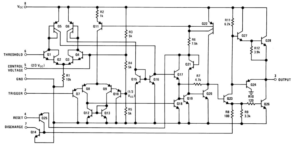
The internal architecture of the 555 timer consists of two voltage comparators, a flip-flop, a discharge transistor, and a resistor divider network. The comparators compare the input voltage to preset reference levels, determining the state of the flip-flop. The discharge transistor is used to reset the timing capacitor in monostable mode, while the resistor divider sets the threshold and trigger levels for the comparators.
The versatility of the 555 timer is further enhanced by its ability to interface with various components such as resistors, capacitors, and diodes, allowing for customizable timing intervals and output characteristics. Its wide supply voltage range, typically from 4.5V to 15V, and low cost make it an ideal choice for both hobbyist projects and professional applications. The 555 timer continues to be a fundamental building block in electronic circuit design, demonstrating its enduring relevance in the field of electronics.The 555 timer. A chip so versatile that it has been used in everything from toys to spacecraft. A chip that can act as an oscillator, a schmitt trigge.. 🔗 External reference
Related Circuits

A digital stopwatch or digital timer circuit schematic is constructed using the timer IC LM555 and the 4-digit counter IC MM74C926, which is paired with a multiplexed 7-segment LED display. The digital stopwatch circuit utilizes the LM555 timer IC configured...
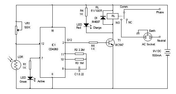
Timer for Charger Circuit Diagram. This timer circuit assists in maintaining the battery in optimal condition by enabling automatic charging for 5 to 6 hours daily, allowing the device to be left unattended. The timer circuit for the charger is...
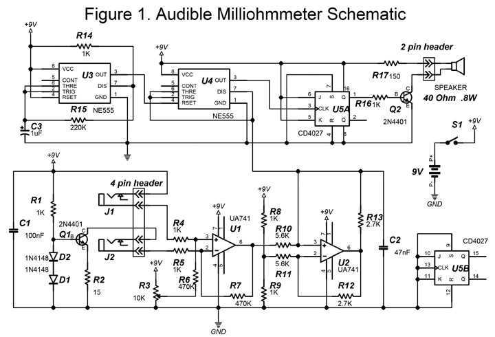
This project uses a four-point resistance measurement process also known as the Kelvin method. This procedure uses a current source to determine the value of an unidentified resistance. A constant current flows through the unknown resistance and the voltage...
Pulse Generator kit will generate a frequency in KHz which can form a good test gear project. This kit is based on the classic LM555 timer IC. Input - 12 VDC Max @ 40 mA. Range - jumper selectable...
This is an SCR timer circuit. In this circuit, an SCR is utilized to activate the final actuator, which is a buzzer. The time constant of the circuit is determined by resistor R1 and capacitor C1. The buzzer will...
This timer circuit is similar to the 5 to 30 minute timer, but when switch S1 is closed, the on/off action of the circuit continues indefinitely until S1 is opened again. A 7555 timer and a low leakage capacitor...