
BTL amplifier composed by a single amplifier
The 13TL amplifier circuit is designed to leverage discrete components to achieve specific performance characteristics, albeit with increased complexity. The BTL (Bridge-Tied Load) amplifier configuration is an efficient design that allows for higher output power while minimizing the number of components required. By employing two amplifiers in a bi-amping configuration, the BTL circuit effectively doubles the output power without necessitating additional power supply voltage, thus enhancing overall efficiency.
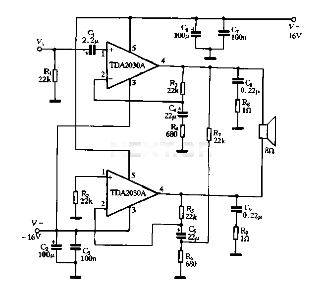
The TDA2030A integrated circuit serves as the core of the BTL amplifier configuration, providing robust performance with a maximum output of 34W when powered by a dual 16V supply. This makes it suitable for driving speakers in various audio applications. The circuit's design facilitates a simplified connection to the load by eliminating the need for a center tap on the power supply, allowing for a more straightforward implementation in audio systems.
In practical applications, the BTL amplifier circuit can be used in home audio systems, car audio systems, and other scenarios where high power output is required from a compact design. The dual power supply configuration ensures that the amplifier can maintain high performance across a range of operating conditions, while the discrete component approach allows for customization and optimization of the circuit to meet specific audio requirements.
Overall, the combination of discrete components and integrated circuits in the 13TL and BTL amplifier designs exemplifies modern audio engineering practices, balancing complexity with performance to deliver high-quality sound output.Discrete components 13TL amplifier, the circuit structure is complex, with an integrated power amplifier circuit of BTL amplifier circuit structure is simple, performance and q uite discrete components. Some integrated amplifier on a single integrated circuit produced two amplifier, called bi-amping, the most likely composition BTL amplifier circuit. Figure t-43 by a single power amplifier TDA2030A composed BTL amplifier circuit. This circuit 16V dual power supply voltage, output 34W maximum power. And in a single amplifier, the maximum output power of 14W
Related Circuits
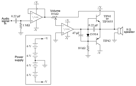
It is advisable to obtain TIP41 and TIP42 transistors, which are closely matched NPN and PNP power transistors with dissipation ratings of 65 watts each. If a TIP41 NPN transistor is unavailable, the TIP3055 (available from Radio Shack) serves...
Headphone Amplifier or Pre-Amplifier Output Stage. This 1-watt amplifier is ideally suited for use as a driver for low-impedance headphones. The headphone amplifier circuit is designed to provide an amplified audio signal to drive low-impedance headphones effectively. Operating at a...
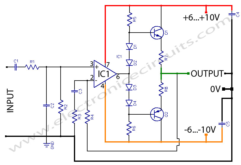
Amplifying circuit diagram to enhance the output current and voltage. An amplifying circuit is designed to increase the amplitude of an input signal, resulting in a higher output current and voltage. This type of circuit is commonly utilized in various...
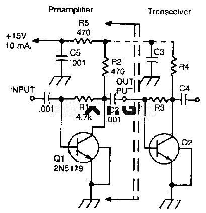
This simple, inexpensive, wideband RF amplifier provides 14 dB gain on two meters without the use of tuned circuits. The RF amplifier described operates within the two-meter band, which typically spans frequencies from 144 to 148 MHz. It is designed...
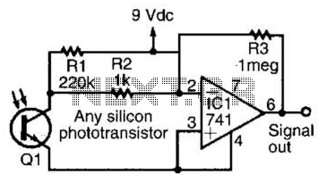
This simple amplifier is compatible with nearly any phototransistor. Although the 741 operational amplifier is designed for use with a split supply, it can also function effectively with a single-sided supply. The described amplifier circuit utilizes the 741 operational amplifier...
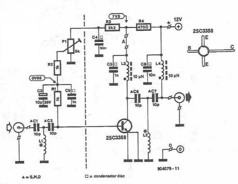
This UHF amplifier circuit project is beneficial for enhancing weak TV signals. The amplifier provides a gain of 10-15 dB within a frequency range of 400 to 850 MHz. To ensure optimal performance and reliability, the PCB tracks should...