
Buck-Based LED Drivers
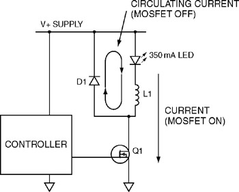
The buck converter circuit operates based on the principle of energy storage and release through inductive components. When the power MOSFET is turned on, current flows through the inductor, causing it to store energy in the form of a magnetic field. The LED load, connected in series with the inductor, experiences a voltage drop that corresponds to the input supply voltage minus the voltage drop across the MOSFET. When the MOSFET is switched off, the inductor releases its stored energy, maintaining the current flow through the LED by utilizing the diode as a path for the current. This process ensures that the LED receives a steady current, which is crucial for its optimal performance and longevity.
To enhance the performance of the buck converter, various control strategies can be implemented. One common approach is to use peak current mode control, which regulates the current flowing through the inductor by monitoring its peak value. This method provides inherent protection against overcurrent conditions and allows for stable operation across varying input and output conditions. Additionally, the design can incorporate feedback mechanisms to adjust the duty cycle of the MOSFET, ensuring that the output current remains constant despite fluctuations in the supply voltage or load conditions.
The efficiency of buck converters is primarily influenced by several factors, including the on-resistance of the MOSFET, the forward voltage drop of the diode, and the quality of the inductor. Selecting components with low losses and optimizing the layout to minimize parasitic inductances and capacitances can significantly enhance overall efficiency. In high-brightness LED applications, where thermal management is also a concern, maintaining high efficiency is crucial to prevent overheating and ensure reliable operation.
In summary, the buck converter is a versatile and efficient solution for driving LEDs, particularly in applications requiring a stable output current with minimal power loss. Its simplicity, coupled with the ability to achieve high efficiency, makes it a preferred choice among engineers designing LED driver circuits.The first switching LED driver that we will study is the buck converter. The buck converter is the simplest of the switching drivers, and is a step-down converter for applications where the load voltage is never more than about 85% of the supply voltage. The limit of about 85% is due to switching delays in the control system. In a buck converter c ircuit, a power MOSFET is usually used to switch the supply voltage across an inductor and LED load connected in series. The inductor is used to store energy when the MOSFET is turned on; this energy is then used to provide current for the LED when the MOSFET is turned off.
A diode across the LED and inductor circuit provides a return path for the current during the MOSFET off time. A simple schematic is shown in Figure 5. 1. Buck converters are an attractive choice for LED drivers in offline and in low voltage applications as they can produce a constant LED current at very high efficiencies.
A peak-current-controlled buck converter can give reasonable LED current variation over a wide range of input and LED voltages and needs no design effort in feedback control design. Coupled with the fact that these converters can be designed to operate at above 90% efficiencies, the buck-based driver becomes an attractive solution to drive high brightness LEDs.
🔗 External reference
Related Circuits
The VU meter operates in conjunction with the integrated amplifier circuit. The audio signal is processed by the audio amplifier circuit, which drives the VU meter to display the audio level. The VU meter circuit is designed to visually represent...
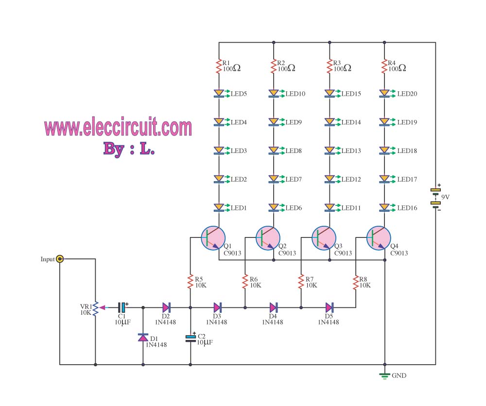
A 4-position slide switch is utilized to activate different colored LEDs based on its position. Additionally, it is required to adjust the output frequency of a 555 timer operating in astable mode to drive a piezo buzzer. The challenge...
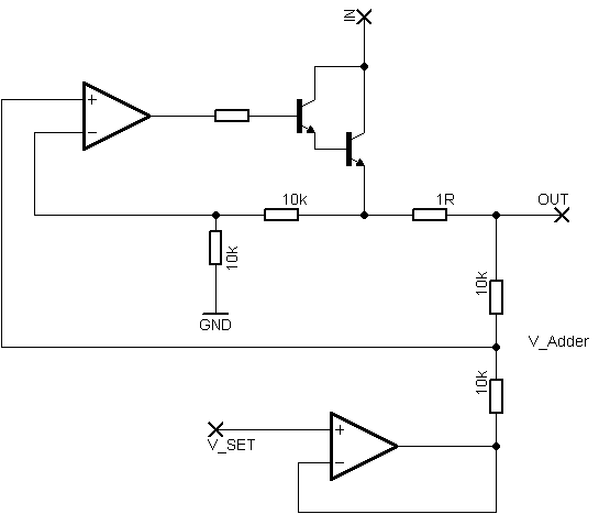
Rsense will cause Q2 to conduct when a threshold of approximately 0.65V is reached. Rbias will determine the extent of this limitation, although this aspect remains unclear. Particularly, if Rsense is positioned on the high side, simply activating Q2...
This circuit utilizes two quad op-amps to create an eight LED audio level meter. The op-amp employed in this circuit is the LM324, a widely used integrated circuit that is readily available from numerous electronic component suppliers. The 1K...
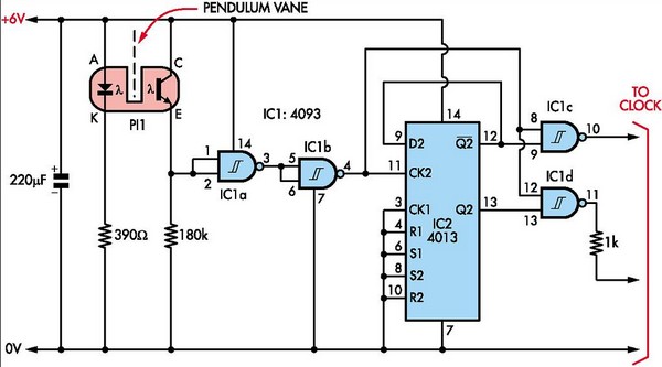
This document outlines the construction of a pendulum-controlled clock designed for high accuracy. Although it has a retro appeal, it represents an intriguing project. The project requires a spare quartz clock, which must be modified by isolating two pads...
This sound-controlled lighting circuit design is utilized to adjust the brightness of connected lights in synchronization with captured sound. The sound-controlled lighting circuit operates by detecting audio signals through a microphone or sound sensor. The circuit typically consists of several...