
build an illuminated hi end digital clock
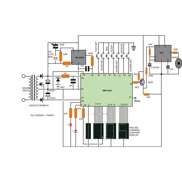
The digital clock circuit utilizes the MM5402 clock IC, which serves as the primary timekeeping component. This integrated circuit is designed to provide accurate timekeeping and is capable of driving a 7-segment LED display to show hours and minutes. The MM5369 clock generator IC complements the MM5402 by generating the necessary clock signals, ensuring synchronization and precision in time display.
The circuit design includes several additional components to enhance functionality. A potentiometer can be integrated to allow for slow/fast time adjustments, enabling users to calibrate the clock as needed. The sleep timer feature can be implemented using a simple timer circuit, which can be triggered by a button press, allowing the clock to enter a low-power mode after a specified duration.
For the alarm function, a piezo buzzer can be connected to the output of the MM5402. The alarm can be set by using additional switches that allow users to program the desired wake-up time. The snooze feature can be achieved by incorporating a momentary push button that temporarily silences the alarm for a preset duration before it sounds again.
Battery backup is crucial for maintaining timekeeping during power outages. A rechargeable lithium-ion battery can be used in conjunction with a charging circuit to ensure that the clock continues to function even when disconnected from mains power. A diode can be added to prevent reverse current from the battery, ensuring that the circuit remains safe and functional.
The complete circuit diagram should clearly illustrate the connections between the MM5402, MM5369, and the supporting components, including the display, buttons for setting the time and alarm, and the battery backup system. Proper labeling of each component will facilitate easier assembly and troubleshooting for individuals looking to replicate this digital clock design.Making a hi-end, accurate digital LED clock today is as easy as cooking noodles. The article explains how a digital clock can be made using over the counter electronic chips like the National s MM5402 clock IC and a handful of other components. This single chip along with a clock generator IC MM5369 together provides some outstanding features other than the usual time displays.
Features like slow/fast time setting, sleep timer, alarm with snooze and battery back-up are all included in this proposed circuit of a digital clock. Complete circuit diagram is enclosed herein.. 🔗 External reference
Related Circuits
This design is based on a publication by Milan Lulic in the German magazine elektroModell. Lulic's design utilizes surface mount technology (SMT), while this version employs standard off-the-shelf components, making it more accessible for hobbyists. For those interested in...
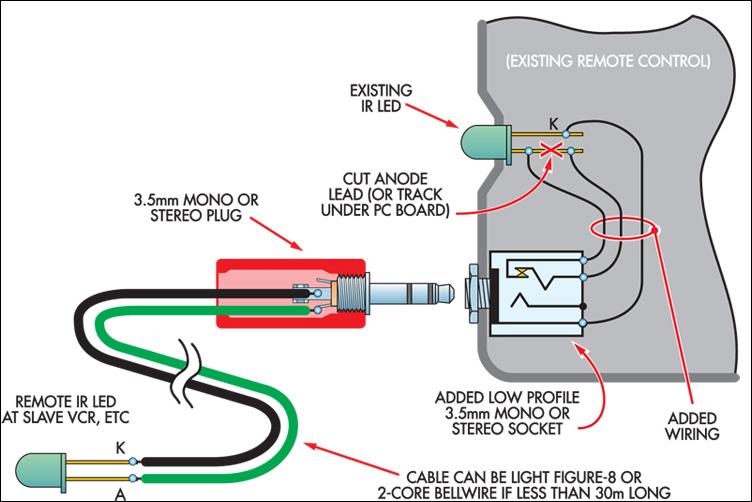
This ultra-simple remote control extender is ideal for use with a hidden video recorder. The recorder is a Panasonic NV-SD200 and is employed as part of a camera surveillance system. A PICAXE-08-based circuit detects events and controls the recorder....
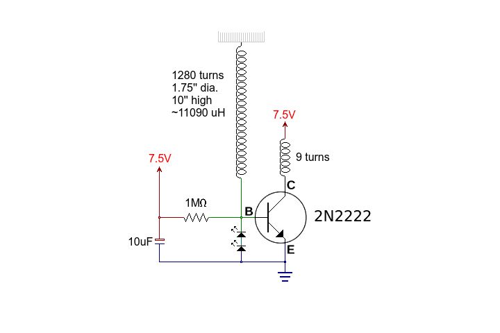
This circuit is straightforward. The accompanying graphics and images provide all necessary details. After gathering all materials, connect the transistor according to the provided schematic. The circuit in question is a basic transistor circuit that serves as an introductory project...
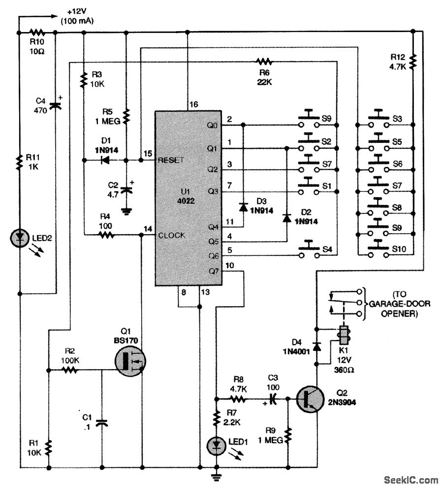
This circuit relies on the input of a correct sequence code. An incorrect number that is not part of the code triggers a reset of the circuit. When the correct code is entered, Q2 activates relay K1 for a...
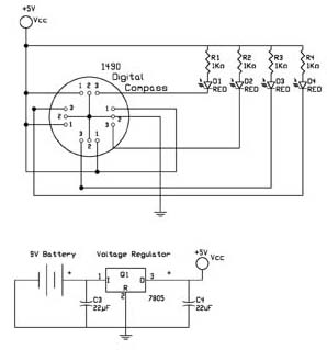
The first test circuit is one of the simplest designs that can be created around the device. The sensor is depicted in the schematic as if viewed from above, showing the 12 leads below. The circuit incorporates four LEDs...
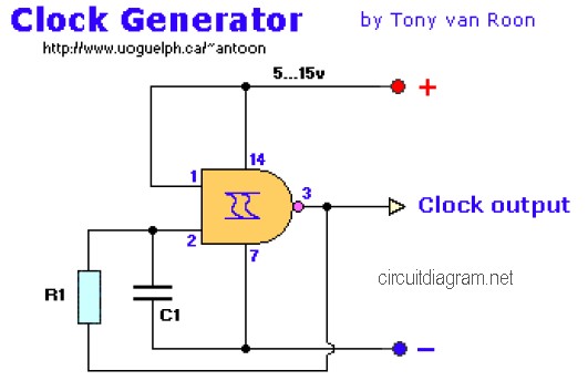
The following diagram is the clock generator circuit diagram built using NAND gate logic integrated circuits (ICs). The circuit can utilize either the IC 7400, which is a TTL type, or the IC 4011, which is a CMOS type....