
Simple Infrared Remote Control Extender
The described remote control extender employs a PICAXE-08 microcontroller, which is a versatile and compact device suitable for handling low-power tasks. The circuit is designed to interface with the Panasonic NV-SD200 video recorder, which is part of a surveillance setup. The functionality of the system revolves around event detection and control signaling, which is achieved through the microcontroller's programming.
The LED indicator serves a dual purpose: it not only provides visual feedback regarding the number of events detected but also acts as a status light for the user. This feature enhances user interaction, allowing for immediate awareness of system activity. The design incorporates an additional 5mm infrared LED strategically placed to ensure optimal line-of-sight communication with the recorder. This LED is connected via light-duty figure-eight cable, which is both flexible and capable of extending the distance between the remote control and the recorder up to 30 meters, thus offering significant versatility in installation.
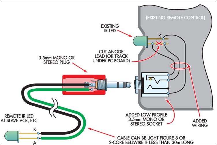
To modify the existing remote control, a careful interruption of the circuit to the anode of the current infrared LED is necessary. This modification allows for the integration of a 3.5mm headphone socket, which facilitates the connection of the new LED while maintaining the functionality of the original remote. The design consideration of allowing the original LED to operate normally when the jack is unplugged ensures that users can revert to the standard operation without any hassle.
In cases where space constraints exist within the remote control casing, the use of a short flying lead with a molded in-line socket provides a practical solution, ensuring that the design remains compact and functional. Overall, this remote control extender design is an efficient and effective solution for extending the range of infrared control for the Panasonic NV-SD200, while also being conscious of power consumption and user convenience.This ultra-simple remote control extender is ideal for use with a hidden video recorder. The recorder is a Panasonic NV-SD200 and is used as part of a camera surveillance system. A PICAXE-08-based circuit is used to detect events and control the recorder. It also flashes a LED near the monitor to indicate the number of events since last viewing. S trangely, the NV-SD200 model refused to work with a number of commercial infrared remote control extenders, hence the need for this design. As a bonus, it uses less power than a traditional extender (no plugpacks) and the remote can still be used in the normal manner.
As shown, an additional 5mm infrared LED is mounted directly in front of the equipment to be controlled. This is cabled back to a convenient location near the monitor and terminated in a 3. 5mm plug. To modify the remote control unit, break the circuit to the anode of the existing infrared LED and wire in a 3.
5mm headphone socket. In most cases, the LED will be accessible without dismantling the circuit board. The purpose of the socket is to allow the existing infrared LED to operate normally when the jack is unplugged. If the socket won`t fit inside the case, then a very short flying lead with a moulded in-line socket can be used instead.
By using light-duty figure-eight cable, the transmitting LED could be 30m or more from the hand-held remote control without problems. 🔗 External reference
Related Circuits
To achieve optimal performance as a low noise, high input impedance device, the preamplifier and tone control utilize JFET technology. The circuit is designed to minimize harmonic distortion levels. The use of Junction Field Effect Transistors (JFETs) in the preamplifier...
For the regulation it needs a voltmeter (with needle better) and charge 50W/5W. Connect charge 50W in the place of aerial, with the voltmeter in the exit voltmeter. Be supplied the transmitter with + 12V. It will be supposed...
The circuit is designed to enable rapid changes in motor speed and direction by utilizing four outputs to drive a MOSFET H-bridge. The lower rail power MOSFETs are N-channel devices, while the upper rail MOSFETs are P-channel. All MOSFETs...
The circuit diagram of an IC Controlled Emergency Light with Charger, also known as a 12V to 220V AC inverter circuit, is presented here. This circuit features automatic activation of the light during mains failure and includes a battery...
This Project is used to control a single phase Motor from any where in the world through the telephone. The circuit consists of a DTMF tone detector and a powerful 8 bit Microcontroller AT89S52. The Microcontroller senses the DTMF...
In certain applications, it is crucial to allow a motor to operate in only one specific direction, even when the power supply phase sequence is incorrect. This situation may arise due to external factors, such as incorrect wiring after...