
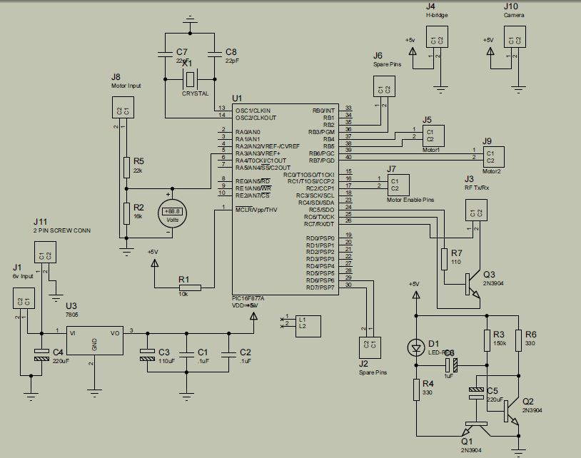
Building an RF Remote Control System For Robotics Control
The Ruf-Bot project exemplifies the integration of RF (Radio Frequency) technology into robotics, showcasing how simple components can be utilized to create functional robotic systems. The primary components typically involved in such projects include microcontrollers, RF transmitter and receiver modules, power supplies, and various sensors or actuators depending on the intended functionality of the robot.
In constructing the RF transmitter and receiver, it is crucial to select modules that operate within compatible frequency ranges, such as 433 MHz or 2.4 GHz, which are commonly used for short-range communication. The transmitter module is connected to the microcontroller, which sends control signals based on user input or pre-programmed instructions. The receiver module, on the other hand, receives these signals and relays them to the microcontroller for processing, enabling the robot to respond to commands.
When designing the circuit on a breadboard, careful attention must be paid to the layout to minimize interference and signal degradation. The metal traces on the breadboard can introduce capacitance, which may lead to unintended circuit behavior. It is advisable to keep the wiring short and organized, avoiding unnecessary loops that could act as antennas and pick up noise. Additionally, using decoupling capacitors near the power pins of the microcontroller and RF modules can help stabilize the power supply and reduce noise.
Power management is another critical aspect of the project. A suitable power supply must be chosen to ensure that both the microcontroller and RF modules operate within their specified voltage ranges. Battery packs or regulated power supplies are common choices, and incorporating a voltage regulator may be necessary to maintain stable operation.
Programming the microcontroller using PicBasic involves writing code that defines the behavior of the RF transmitter and receiver. This includes setting up the communication protocol, managing input from sensors, and controlling actuators such as motors or servos to achieve desired movements or actions. Debugging the code and testing the RF communication range are essential steps to ensure reliable operation of the Ruf-Bot.
In conclusion, the Ruf-Bot project highlights the potential of combining inexpensive components with creative engineering to build sophisticated robotic systems. By understanding the intricacies of RF communication and circuit design, users can develop their own unique robotic creations, enhancing their skills and knowledge in electronics and programming.With a handful of inexpensive components, a little creativity, and the power of PicBasic, you can build some pretty outstanding robotics creations as Rob Arnold proves with his Ruf-Bot project. RF remote control is just way too cool not to use in your designs, but if you`re a newbie like me it`s difficult to successfully build solid RF transmitters and receivers on your own.
When I started out I didn`t realize that the larger breadboard I was working off of was causing a lot of the signal deviance because the metal traces on the breadboard worked like small capacitors, and changed my circuit dynamics. 🔗 External reference
Related Circuits
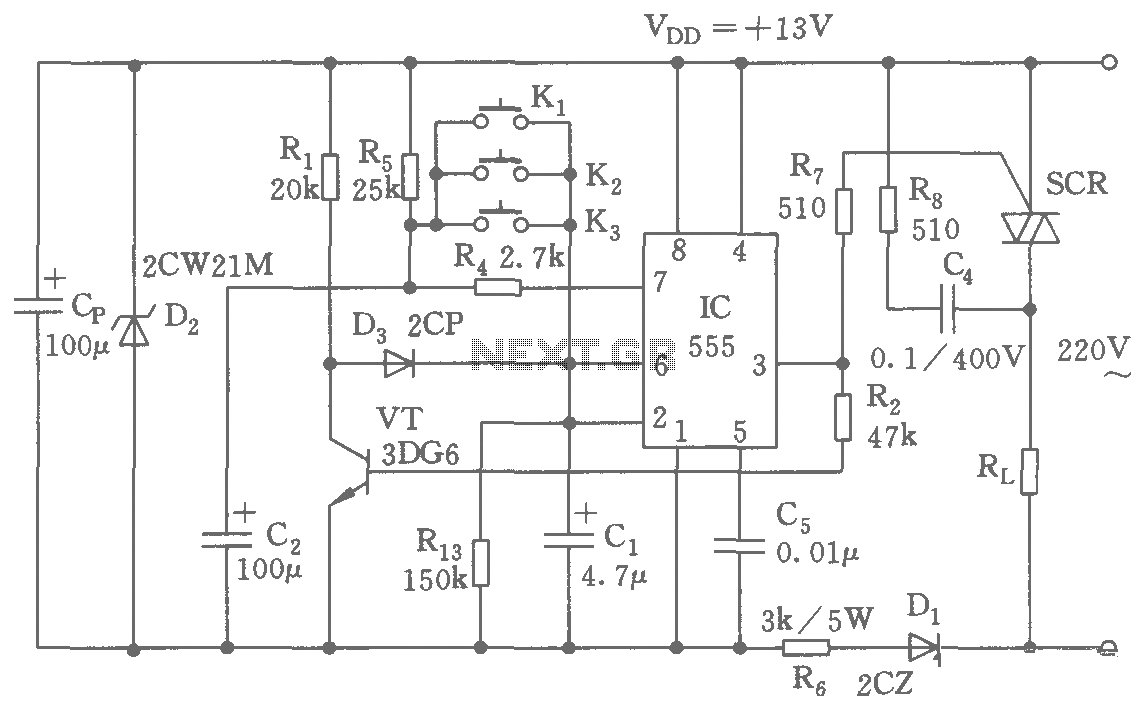
The switching circuit consists of a buck rectifier circuit, a bistable trigger circuit, and a thyristor control circuit, enabling remote control for electrical equipment to be turned on or off. The buck rectifier circuit supplies the controller with a...
The mine railway connects the national railways and intermediate links of the mining area, serving as an important component of the railway transport network. Statistics indicate that the Chinese mine railway extends over 20,000 kilometers, with numerous road junctions...
It is said that mice are more sensitive to electromagnetic fields, which is why high-voltage grids generally yield poor results in rodent control. The electronic rodent control system described here does not use high-voltage power lines, thus it does...
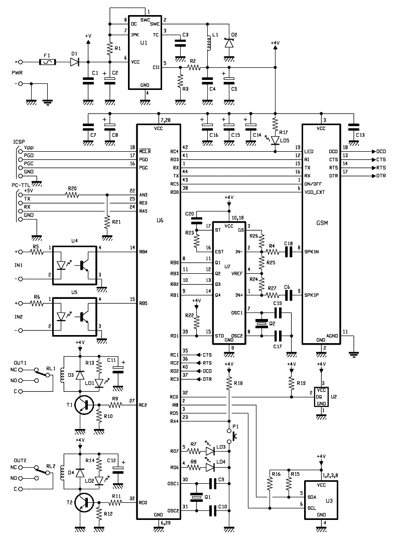
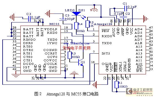
The entire remote control is managed by a PIC that oversees the GSM/GPRS module's operations, monitors room temperature via a Dallas DS1820 smart probe, controls the logical state of two opto-isolated inputs, and sends commands to two relays. Additionally,...
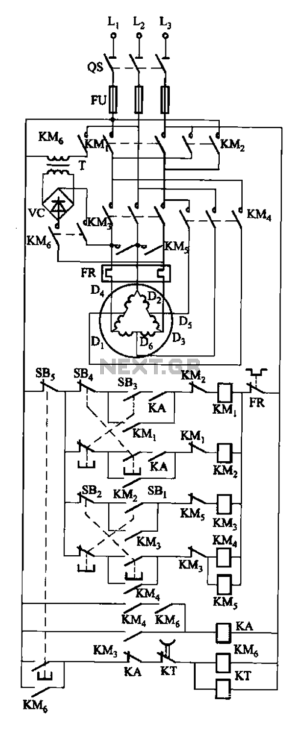
The circuit depicted in Figure 3-108 includes various control buttons: SB3 for the forward button, SI for the reverse button, SBi as the low start button, SB2 for the speed start button, and SBs for the stop button. KMs...
The project is developed by Team Stark, with Gilbert as the leader and team members Martin and Janssen. The tasks have been divided into three parts. The first part includes camera control, login database, installer, and network setup, which...
Warning: include(partials/cookie-banner.php): Failed to open stream: Permission denied in /var/www/html/nextgr/view-circuit.php on line 713
Warning: include(): Failed opening 'partials/cookie-banner.php' for inclusion (include_path='.:/usr/share/php') in /var/www/html/nextgr/view-circuit.php on line 713