
Tube in a Tube Clock

The nixie clock circuit operates by utilizing a high-voltage supply derived directly from the mains, which is a notable feature of its design. The BC550 transistors serve as drivers for the nixie tubes, allowing for effective operation at high voltages despite their low BVceo rating. The careful selection of components ensures that the clock performs reliably while maintaining safety standards.
The clock's design incorporates a dropper capacitor power supply, which allows for the direct connection to the mains without the need for a transformer. This is achieved by using a capacitor to limit the current flowing into the controller circuit, which operates at a lower voltage. This method is efficient and reduces the overall size of the clock, making it suitable for unique casing options like a glass test tube.
Safety is emphasized in the design, with a focus on isolating the high-voltage components from user-accessible parts. The use of a cord switch not only facilitates the on/off function but also provides a means to set the time, integrating user interaction into the design seamlessly.
The ambient lighting feature adds a decorative element to the clock, enhancing its visual appeal during low-light conditions. The three-color LED creates a dynamic display that can transform the atmosphere of a room, making the clock not just a timekeeping device but also a piece of art.
The schematic representation of the power distribution grid highlights the importance of understanding electrical safety. The distinction between the live wire and the neutral wire is crucial for ensuring safe operation, particularly in devices that connect directly to the mains. Proper insulation and housing of the circuit are essential to prevent accidental contact with live components, reinforcing the need for safety in the design of this nixie clock.The clock described on this page is the result of both events, a simple single digit nixie clock with some interesting features, but without any difficult components. This clock first of all demonstrates that it is possible to use standard, low-voltage, general puspose, small-signal transistors like the BC550, as nixie drivers.
Since I can imagine that it will be a surprise to most people, that a transistor with a BVceo of 50V can be used in a 200V application, I have gone to quite some length to explain it, starting from basic semiconductor theory. The high voltage supply for the nixie in this clock is directly taken from the mains. This works perfectly, but it has some serious implications with respect to safety. The first section on this page deals with this issue; read it carefully! However, the clock is completely safe as long as a completely isolating case is used, and as long as no metal parts of the circuit can be touched while it is connected to the mains.
The circuit for this clock is so small, that an elegant glass test-tube could be used as a case! For safety reasons, the mains on/off switch, in this case a simple cord switch, is used to (besides switch the clock on and off), set the time. How this works is explained later on. By minimizing the power consumption of the controller circuit, it additionally was possible to feed the low-voltage controller circuit directly from main, without the need for a transformer!
How it works is explained in the section Dropper capacitor power supply. The last point concerning this clock that needs introduction is the ambient lighting feature. On the backside of the clock a three color LED is mounted which produces an endless sequence of random colors (Fig. 1). This produces in the evening and at night a nice glow on the wall behind the clock, which really brings the clock to life!
I first used this feature in the clock for my son Geert. It was a huge success and you should really try it! In a circuit which is directly fed from the mains, the circuit is connected via a direct galvanic connection to the mains. Before I start with the description of the clock circuit, I have to explain why directly mains fed circuits are so dangerous, much more dangerous than circuits that use the same high voltage but derived from a transformer.
Figure 2 shows a simplified schematic drawing of the final part of the power distribution grid that delivers the power to your home, connected to an appliance that uses a transformer. Lets for the sake of this example assume that it is a 240V to 180V transformer used to feed the NIXIE tubes.
In the last distribution station the high voltage from the power grid is transformed down to 240V, the mains voltage we have in Europe. The power is delivered through two wires. One of these wires is called the "life wire" or the "phase wire". The return wire is called the "null" or "ground" wire. It is important to note that at 🔗 External reference
Related Circuits
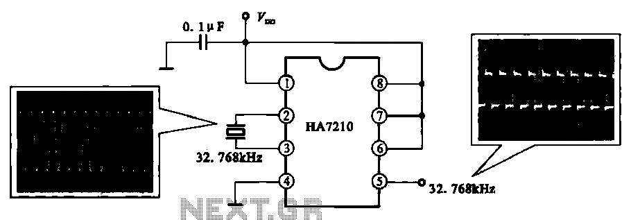
This circuit illustrates a 32.768 kHz micro-power clock oscillator, suitable for use in mobile phones, laptop computers, and home appliances. It generates a clock signal that can be utilized in various applications. The 32.768 kHz micro-power clock oscillator circuit is...
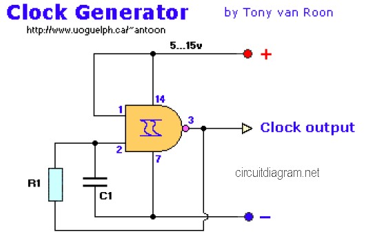
The following diagram is the clock generator circuit diagram built using NAND gate logic integrated circuits (ICs). The circuit can utilize either the IC 7400, which is a TTL type, or the IC 4011, which is a CMOS type....
Miniature vacuum tubes utilizing cathodes made of high-field-emitting carbon nanotubes are being researched at Agere Systems in Murray Hill, NJ. A triode with an amplification factor of 4 has been developed, featuring an anode-cathode spacing of 220 µm, with...
This phono stage significantly outperformed a sub-mini phono preamp. The phono preamp was exceptionally quiet when paired with a vintage Grado 8MR cartridge (not MC). It does not have a vintage sound; while it is pleasant and clearly tube-based,...
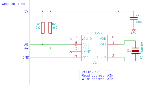
The Arduino displays the time and date on an optional LCD and in the Arduino IDE serial monitor window. A PCF8563 real-time clock (RTC) integrated circuit (IC) is utilized to generate the time and date. The time and date...
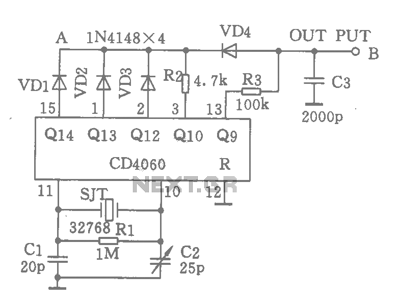
A CD4060 integrated circuit, combined with a 32,768 Hz crystal oscillator, is utilized to create a highly accurate clock source that generates 60 pulses per second. The operation is based on the division of the 32,768 Hz pulse output...