
Burglar Alarm With Timed Shutoff

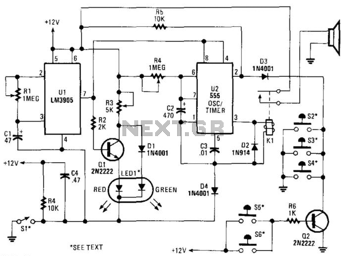
The circuit operates based on the closure of a sensor input (SI), which initiates the power supply to a dual timer integrated circuit (U2). The dual timer is configured to create a delay based on the capacitance value of capacitor C2. When the sensor is activated, the timer begins its timing cycle, and after a specified duration, determined by the characteristics of capacitor C5, the output at pin 9 of U2 transitions to a low state.
This low state triggers the optoisolator's transistor to turn off, which in turn interrupts the anode current flowing to the silicon-controlled rectifier (SCR1). As a consequence, the relay (K1) is de-energized, effectively resetting the system. The timing relationships are critical, as the equation provided indicates that the ON time (Ton) is influenced by the resistive and capacitive components in the circuit. Specifically, the ON time is calculated as the difference between the product of resistance R7 and capacitance C5, and the product of resistance R6 and capacitance C2.
The condition that (i6x C2) is less than (R7xC5) ensures that the timing cycle is appropriately configured to avoid premature triggering of the SCR1, thereby ensuring reliable operation of the system. This design reflects a careful balance of timing elements, providing a robust mechanism for controlling power to the relay based on sensor input. When SI (sensor) is closed, power is applied to U2, a dual timer. After a time determined by C2, CI is ene rgized after a predetermined time determined by the value of C5, pin 9 of U2 becomes low, switching off the transistor in the optoisolater, cutting anode current of SCR1 and de-energizing Kl. The system is now reset. Notice that (i6x C2) is less than (R7xC$). The ON time is approximately given by:(R7xC5)-(R6xC2) = Ton
Related Circuits
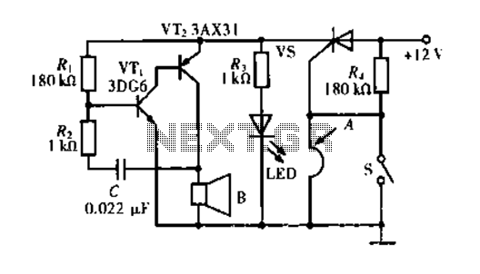
The circuit operates based on a principle where the SCR (Silicon Controlled Rectifier) trigger is grounded, keeping it in the off state. When a burglar triggers the alarm, a voltage is supplied to the SCR trigger, turning it on....
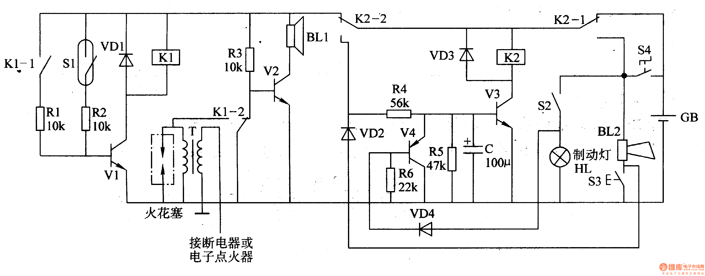
The circuit comprises a trigger circuit, an alarm control circuit, and a reset circuit for the alarm. The trigger circuit includes mercury switches (S1), a resistor, transistors (V1), and a relay (K1). The alarm control circuit is made up...
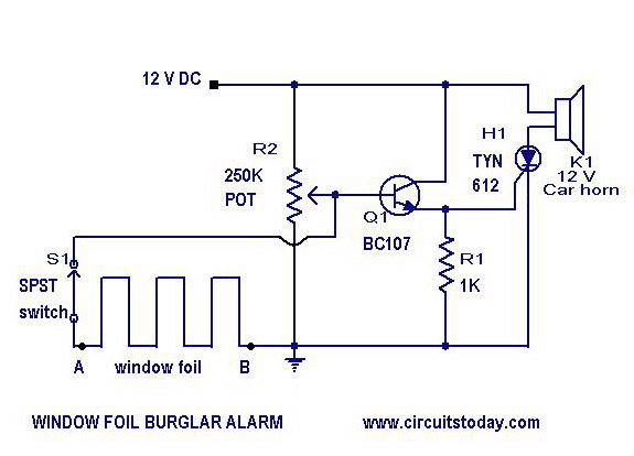
A simple burglar alarm circuit diagram and schematic. This can be used as an anti-theft alarm by attaching the burglar alarm circuit to window foil. The burglar alarm circuit is designed to provide a basic security solution for residential or...
SI is an external key switch. The alarm allows a delay of 0 to 45 seconds after SI is operated before the circuit is armed. During this period, LED1 lights up green. After this delay, LED1 lights red, indicating...
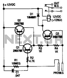
This circuit functions as a flood alarm using several bipolar transistors. When liquid comes into contact with the probes, a leakage current biases Q1, Q2, and Q3 (configured as a direct current-coupled amplifier) into conduction, thereby activating the relay....

The operating voltage for capacitors C1 and C2 should be raised to 25V if a 12V energy source is used. A general guideline is that the operating voltage of capacitors should be at least double the supplied voltage; for...