
Flood Alarm
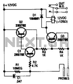
The flood alarm circuit is designed to detect the presence of liquid through the use of probes that serve as sensors. The circuit primarily consists of three bipolar junction transistors (BJTs) labeled Q1, Q2, and Q3. When liquid bridges the gap between the probes, it creates a leakage current that flows into the base of Q1. This current is sufficient to turn Q1 on, allowing it to conduct.
As Q1 conducts, it provides a biasing current to Q2, which is also configured to operate in the active region. The conduction of Q2 further drives Q3, which is arranged as a direct current-coupled amplifier. The amplification provided by Q3 enhances the signal, ensuring that even a small leakage current can effectively trigger the next stage of the circuit.
Once Q3 is activated, it energizes a relay that is connected to its collector. The relay acts as a switch that can control higher voltage and current loads, allowing it to interface with an alarm system or other alert mechanisms. The contacts of the relay can be wired to sound an alarm, activate a light, or send a signal to a monitoring system, thereby providing a reliable warning of flooding conditions.
To ensure proper operation, the circuit should be designed with appropriate biasing resistors for the transistors and a suitable relay that can handle the desired load. Additionally, the probes should be made from corrosion-resistant materials to ensure longevity and reliability in detecting liquid presence. This flood alarm circuit is a practical solution for early detection of water leaks or flooding, providing timely alerts to prevent damage. Using a few bipolar transistors, this circuit acts as a flood alarm. When liquid touches the probes, leakage current biases Ql, Q2, and Q3 (a dc-cou-pled amplifier) into conduction, which activates the relay. The contacts can be hooked into the alarm system. 🔗 External reference
Related Circuits
A simple light fence security beeper is presented. This circuit can function as a door alarm, gate alarm, pathway alarm, etc. It can be powered by any 12 Volt DC power supply. The operation of this circuit is straightforward....
Locker Guard Circuit Diagram. This compact circuit is designed to protect a locker or almirah from burglary. If the locker is opened while in the armed state, the circuit triggers a loud police siren to deter the burglary attempt. The...
The alarm detector circuit operates differently from the Ultrasonic Alarm (1). In Ultrasonic Alarm (1), an alarm output is triggered by the detection of a reflected wave from an object during the setup time. Conversely, in this circuit, an...

A nightlight combined with a wake-up alarm has been developed. This nightlight incorporates six LEDs that activate when a photosensor detects low ambient light levels. Additionally, a buzzer plays a cheerful tune when ambient light levels increase again. The...
The frequency is controlled by pin 5 of the integrated circuit (IC). When the power supply is activated, the capacitor charges gradually, which alters the voltage at pin 5 of the IC, causing the frequency to increase incrementally. Once...

The working voltage of capacitors C1 and C2 should be increased to 25V if a 12V power source is used. A general guideline is that the operating voltage of capacitors should be at least double the supplied voltage; for...