
Busy Telephone line Indicator
The circuit described is designed to provide visual indicators for phone line usage, specifically for situations where simultaneous use of a modem or fax machine occurs alongside phone calls. It uses two light-emitting diodes (LEDs) to indicate the status of the phone line: a red LED (LED1) illuminates when the line is in use, while a green LED (LED2) indicates when the line is available. The circuit operates without requiring any external power supply, which enhances its versatility and ease of installation.
The design is built around a perf board, making it straightforward to assemble and mount within the housing of a phone. Key components include two NPN transistors (Q1, Q2 - 2N3392), which act as switches, controlling the LEDs based on the line's status. The bridge rectifier (BR1) converts the alternating current (AC) from the phone line into direct current (DC), allowing the LEDs to function correctly. The circuit also incorporates several resistors (R1 to R5) to limit current and ensure proper operation of the transistors and LEDs.
LED1 and LED2 are designed to flash in response to incoming calls, providing a visual cue that the phone line is active. Care must be taken during installation to avoid mixing the Tip and Ring connections, as the ring voltage can be substantial (between 90 to 130 volts). It is advisable to consult with the local phone service provider before installation, as regulations may vary by location and could necessitate an inspection.
If the circuit introduces distortion on the phone line, a 680-ohm resistor can be added in series with one of the incoming line wires and the bridge rectifier to mitigate this issue. This addition helps to ensure that the circuit operates effectively without compromising the quality of phone calls. Overall, this simple yet effective circuit can significantly enhance the functionality of a phone line used in conjunction with modems or fax machines.Have you ever been using the modem or fax and someone else picks up the phone, breaking the connection? Well, this simple circuit should put an end to that. It signals that the phone is in use by lighting a red LED. When the phone is not in use, a green LED is lit. It needs no external power and can be connected anywhere on the phone line, even mounted inside the phone.
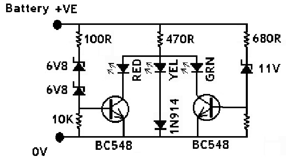
Note: This circuit may cause problems for some when used. You may want to build a different circuit. This is a very simple circuit and is easily made on a perf board and mounted inside the phone. LED1 and LED2 flash on and off while the phone is ringing. Do not worry about mixing up the Tip and Ring connections. The ring voltage on a phone line is anywhere from 90 to 130 volts. Make sure no one calls while you are making the line connections or you'll know it. In some countries or states you will have to ask the phone company before you connect this to the line. It might even require an inspection. If the circuit causes distortion on the phone line, connect a 680 ohm resistor in between one of the incoming line wires and the bridge rectifier.
R1=3.3K 1/4 W Resistor R2=33K 1/4 W Resistor R3=56K 1/4 W Resistor R4=22K 1/4 W Resistor R5=4.7K 1/4 W Resistor Q1, Q2=2N3392 NPN Transistor BR1=1.5 Amp 250 PIV Bridge Rectifier LED1=Red LED LED2=Green LED Wire, Case, Phone Cord 🔗 External reference
Related Circuits
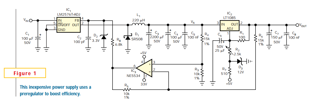
Linear regulators are easy to implement and have better noise and drift characteristics than switching approaches. Their largest disadvantage is inefficiency: excess energy dissipated as heat. Several well-known techniques are available to minimize the input-to-output voltage across a linear...
This circuit was designed to provide a valuable test equipment tool for sound reinforcement systems like guitar amplifiers and the like. Used in conjunction with a signal generator it can be of considerable help in setting and controlling levels...
The IN914 (small glass diode) and the zener diodes have bands on their bodies that must be oriented according to the diagram provided. The bands are located at the cathode end of the diodes. A magnifying glass can assist...
Designing various electronic circuit systems (synthesizer, modem, decoder, data converter, etc.) often requires a frequency modulator subsystem. An FM modulator is a crucial component in these systems. An FM modulator is an electronic device that encodes information in a carrier...
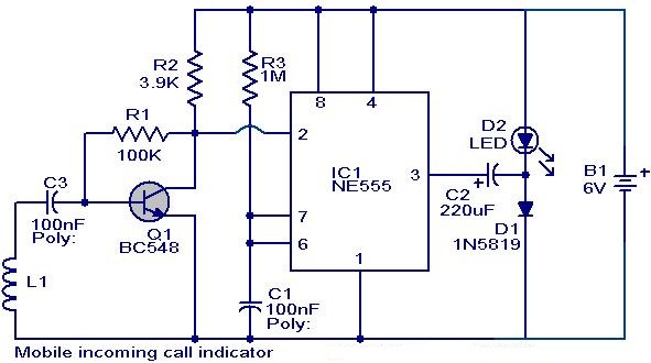
This circuit can be utilized to eliminate the annoyance of mobile phone rings while at home. It provides a visual indication when placed near a mobile phone, even if the ringer is turned off. When a call is received,...
The circuit is designed for individuals who spend extensive hours exploring the various resources of this site. Although it comprises only three components, it effectively indicates whether the telephone line has been released after a prolonged connection via modem...
Warning: include(partials/cookie-banner.php): Failed to open stream: Permission denied in /var/www/html/nextgr/view-circuit.php on line 713
Warning: include(): Failed opening 'partials/cookie-banner.php' for inclusion (include_path='.:/usr/share/php') in /var/www/html/nextgr/view-circuit.php on line 713