
Peak Level Indicator
The described circuit functions as a test equipment tool specifically tailored for sound reinforcement systems, such as guitar amplifiers. Its primary role is to facilitate the testing and calibration of audio equipment by allowing users to generate and manipulate audio signals effectively. The circuit typically incorporates a signal generator, which produces a range of test tones or signals that can be fed into the amplifier or audio system under test.
The design of the circuit may include several key components, such as operational amplifiers for signal conditioning, resistors for setting gain levels, and capacitors for filtering unwanted noise. Additionally, the circuit may feature variable resistors (potentiometers) to allow users to adjust levels and frequencies according to specific testing requirements.
Connections for input and output should be clearly defined, with input terminals for connecting the signal generator and output terminals for interfacing with the amplifier or sound system. It is essential that the circuit is designed to handle a variety of signal levels to accommodate different types of audio equipment.
Furthermore, the circuit may include LED indicators to provide visual feedback on signal presence and levels, enhancing usability during testing. Proper grounding and shielding techniques should be employed to minimize interference and ensure accurate measurements.
Overall, this test equipment circuit serves as a critical tool for audio professionals, enabling precise control and adjustment of sound levels throughout the amplification chain, thereby improving the overall performance and reliability of sound reinforcement systems.This circuit was designed to provide a valuable test equipment tool for sound reinforcement systems like guitar amplifiers and the like. Used in conjunction with a signal generator it can be of considerable help in setting and controlling levels through any amplifying chain.
🔗 External reference
Related Circuits
When the water level is below the steel rods, there is no contact between the metal can and the rods, which are supported by a small insulated wooden board. The circuit built around IC1 draws no current, resulting in...
The schematic represents a water level alarm circuit. This circuit functions as a water level sensor and emits a melodious alarm sound when the two probes within the circuit detect the presence of water. This water level indicator circuit...
This weblog discusses electronic circuit schematics, PCB design, DIY kits, and electronic project diagrams. The 1K resistors in the circuit are significant as they allow the LEDs to activate at different audio levels. While these resistors can be modified,...
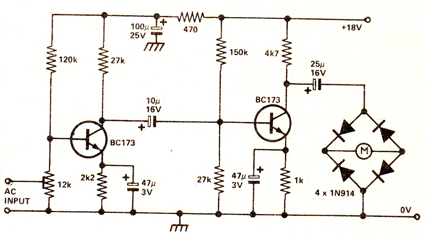
The circuit illustrates a two-stage voltage amplifier that drives a recording level meter. An AC signal input is amplified and rectified, with the resulting DC voltage displayed on the meter. This circuit is compatible with tape recorders or audio...
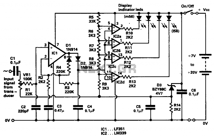
The indicator was designed to display the peak level of small AC signals from various transducers, including microphones, strain gauges, and photodiodes. The circuit responds to input signals within the audio frequency spectrum, specifically from 30 Hz to 20...
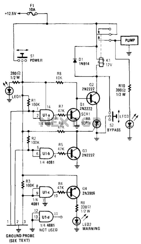
This circuit powers a water pump when the water reaches a predetermined level and turns off when the water recedes to another predetermined point. Gates U1A through U1C have their two inputs tied together and serve as probes placed...