
Time-On Touch Switch

The described circuit employs a 555 timer IC configured in monostable mode, which is ideal for generating a single output pulse in response to a trigger signal. The touch terminal serves as the input for the trigger, which, when activated, causes the 555 timer to generate a high output on pin 3. This output is used to drive the LED1 and the piezoelectric buzzer BZ1. The duration of the output pulse is determined by the resistor R2 and the capacitor C, following the formula T = 1.1 * R2 * C, where T is the time period in seconds.
The circuit is designed to be powered by batteries, which adds versatility and portability, allowing it to be used in various applications without reliance on a fixed power source. The inclusion of a 10-ohm resistor (R1) at the trigger input enhances the circuit's sensitivity, ensuring that even minimal contact at the touch terminal can initiate the activation sequence. This characteristic makes the circuit suitable for applications where ease of use and quick response are critical.
Adjustments to the values of C1 and R2 enable users to customize the ON-time according to specific needs, making the circuit adaptable for different scenarios. The simplicity and effectiveness of this design lend it to various uses, from simple alarm systems to interactive installations, where user engagement is achieved through tactile interaction. The circuit is built around a 555 oscillator (Ul), which is turned on when a trigger is applied by touching the touch terminal to pin 2 of Ul. When activated, LED1 and BZ1 (a piezoelectric buzzer) turn on for the time period set by the values of R2 and C. The ON-time of the touch circuit can be altered by changing the values of Ci and R2. This touch switch can be powered from batteries so that it need not be near a 60-Hz power source for triggering.
The extremely small amount of current supplied to the trigger input through the 10- resistor. Rl, makes the input circuitry very sensitive to any external loading, and it is easily triggered by touching the pickup.
Related Circuits
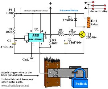
The working voltage of capacitors C1 and C2 should be increased to 25V if a 12V power source is used. A general guideline is that the operating voltage of capacitors should be at least double the supplied voltage; for...
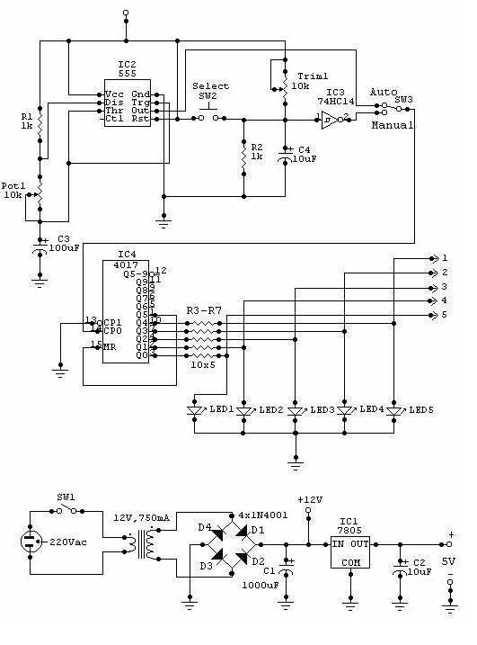
This circuit can be utilized for multiple cameras with a single monitor. The operation can be manual or automatic. In automatic mode, the switch... This circuit is designed to enable the connection of multiple cameras to a single monitor, allowing...
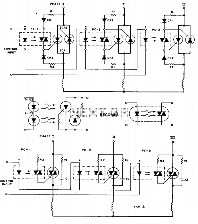
To simplify the following schematics and facilitate easy understanding of the principles involved, the following schematic substitution is used. Note that the triac driver is of limited use at 3-phase voltage levels. The following are three-phase switches for low...
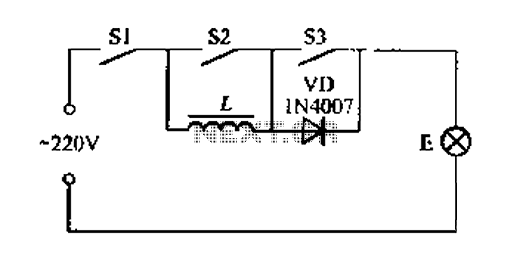
A portable four dimmer switch circuit is illustrated in Figure 8, featuring a four-speed brightness adjustment. When switches S1, S2, and S3 are all closed, the lamp operates at its brightest setting. When S1 and S2 are closed while...
Light Sensitive Switch is a simple project which operates a relay when the light falling on the LDR goes below a set point. More: Input - 12 V @ 55 mA Relay output - NC-C-NO Onboard preset to set the level Power-On...
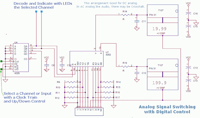
This circuit utilizes a 4052 as a DC Analog Multiplexer. The inputs to this multiplexer must originate from low-impedance output operational amplifiers (OpAmps). The resistors depicted are unnecessary once the signal conditioning OpAmps are connected. However, 100K resistors can...