
By single-phase active power factor correction (APFC) Make up three-phase APF
The described circuit configuration involves multiple components and considerations for effective operation. Each single-phase PFC unit operates independently, allowing for redundancy and increased reliability in the system. The use of isolated DC/DC converters ensures that the output voltage remains stable and regulated, even if one of the PFC units experiences a fault. The ability to connect the system using either a three-phase three-wire or four-wire configuration enhances its adaptability to various applications and installation scenarios.
In terms of power factor correction, the integration of APFC technology is critical in applications where minimizing harmonic distortion is essential for compliance with regulatory standards. The selection of appropriate control chips, such as UC3854 or IR1150, is vital for optimizing the performance of the PFC units. These chips facilitate precise control over the switching actions of the PFC, improving overall efficiency and reducing losses.
The circuit's design can be optimized for specific load requirements, taking into account factors such as input voltage range, expected load variations, and environmental conditions. The implementation of feedback mechanisms within the control strategy allows for real-time adjustments to maintain optimal performance under varying operational conditions.
In conclusion, the proposed circuit architecture offers a robust solution for achieving effective power factor correction in three-phase systems, leveraging the advantages of single-phase PFC technology while addressing the challenges associated with three-phase configurations. The ongoing development and refinement of control chips and circuit designs will further enhance the efficacy and applicability of this technology in the field of power electronics.Tape isolate single-phase PFC that DC/ DC vary make up, make up two cable, PFC of three-phase, that single-phase PFC make up in parallel directly in Ausgang by three single-phase PFC in parallel respectively by three The road is formed by matrix type DC/ DC converter Power factor correction Power Factor CorrecTIon, is abbreviated as PFC Technology, especially active power factor correction Active Power FactorCorrection, is abbreviated as APFC Technology can valid the intersection of inhibition and harmonic wave, single-phase APFC riper in technical research, has had many commercialized specialized control chips already, such as UC3854, IRll 50, LTl508, ML4819. Compared with single-phase power factor correction fairing attachment, three phases PFC fairing attachment have a lot of advantages: 1The input power is high, the rated value of power is reachable several kilowatts the above; 2The single-phase PFC fairing attachment input power is that one is twice as much as quantity that mains frequency changes, but in the three-phase balancing device, the partial summation is zero that the three-phase input power pulses, the input power is a steady state value, the pulsation cycle of three phases PFC fairing attachment output power is only single-phase full wave rect.
1/3, the ripple factor is low, so can use the minor output capacitance of the capacity, thus can realize the dynamical response of more quick output voltage. Become the focal point that numerous scholars are studying, but actually existing and certain difficulty in three-phase APFC technology, and not seen the mature specialized control chip yet.
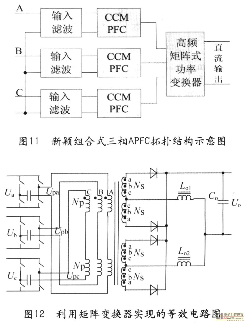
If can exactly formate single-phase APFC circuit simply a piece of three phases APFC circuit, can fully utilize the mature single-phase control chip, produce three phases APFC device of meeting the demands out. Now introduce several kinds of methods that is made up three-phase APFC by single-phase APFC. 1Do not need to study the new topological and control mode, can employ and develop more mature single-phase PFC topologically directly, and corresponding single-phase PFC control chip and control method; 2The circuit is supplied power at the same time by a plurality of single-phase PFC, if some is one-phase breaks down, other quarter-phases can still continue supplying power to load, the circuit has redundant characteristics; Follow an isolated form DC/ DC converter after each single-phase PFC, DC/ DC converter Ausgang stands up in parallel, form a direct-flow loop, supply power to load, as shown in Fig.
1. This kind of circuit can adopt the connection of the three phase three wire system, can also use the three phase four wire system connection, very flexible and very simple. And this kind of circuit can be designed into the single stage form, thus reduce power level and dynamical response faster.
But this kind of circuit is made up of converter of three totally independent single-phase PFCs and DC/ DC, there are many devices that used because of taking 3 and isolated DC/ DC converter, cost great. The switch that the characteristic of the circuit of Fig. 2 is DC/ DC is simple in control comparison, are suitable for the application of the high-power occasion as to other circuit.
But because isolate the influence that the voltage transformer reflects the voltage, the whole-bridge circuit has more high distorted electric current as to anti exciting circuit. Fig. 3 uses constituent three-phase PFC synoptic diagram three single-phase Buck converters, the architectural comparison of the circuit of Model Buck illustrated in Fig.
3 is simple, similar with the whole-bridge circuit, because isolate the influence that the voltage transformer reflects the voltage, it has greater distorted electric current too as to anti exciting circuit, but its harmonic wave can still be limiting more low-level, up to the taking of IEC- 1000. In addition, the magnitude of its realizable power 🔗 External reference
Related Circuits
This power supply circuit is highly stabilized that its output voltage will drop only 0.005% even though the load changes from 0 to 100%. Another excellent capability is that the output voltage will change only by 0.01% if the...
Decorative lights arranged in various moving patterns are visually appealing and have gained significant popularity in today's world. While more complex lighting arrangements may require the use of microcontroller ICs, simpler yet captivating light effects can be generated using...
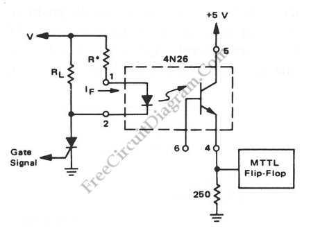
Interfacing high power loads can be accomplished in various ways, including the use of voltage divider resistors, transformers, or optocouplers. The circuit illustrated below employs the optocoupler method. This optocoupler facilitates logic level translation with flexible input, accommodating a...
An 18-year-old electrical engineering student, Chris Rieger, has been developing his levitating light bulb project, aptly named the LevLight Project, for approximately six months. Recently, he shared images and a video of the project, which gained significant attention on...
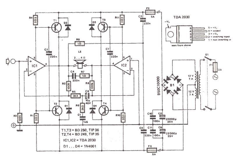
The TDA2030 is a low-cost audio power amplifier capable of delivering high output audio power up to 200 watts with a load impedance of 2 to 4 ohms. This high-power audio amplifier is built around the TDA2030 audio amplifier...
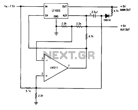
The auxiliary output powers the memory, while the main output powers the system and is connected to the memory store pin. When power goes down, the main output goes low, commanding the memory to store. The auxiliary output then...