
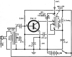
Basic Circuit Modification of Kodak Disposable Camera
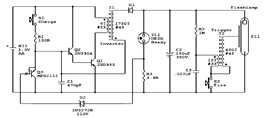
The Kodak MAX Flash Unit circuit is designed to provide a reliable power source for flash photography, utilizing a combination of capacitors, resistors, and semiconductors to achieve optimal performance. The core of the circuit typically includes a high-voltage capacitor that stores energy, which is then rapidly discharged to power the flash bulb when triggered.
Key components in the circuit may include:
1. **Capacitor**: A high-voltage capacitor is essential for storing charge. The capacitance value determines the amount of energy that can be stored, affecting the brightness and duration of the flash.
2. **Transistor**: The circuit may utilize a transistor as a switch to control the discharge of the capacitor. When the flash is activated, the transistor allows current to flow, discharging the capacitor through the flash bulb.
3. **Resistors**: Various resistors in the circuit help to control the current flow and protect sensitive components from excessive voltage.
4. **Diodes**: Diodes may be incorporated to prevent back EMF from damaging other components when the flash discharges.
5. **Trigger Mechanism**: A trigger circuit is often included, which can be activated by a button or a signal from a camera. This mechanism ensures that the flash fires at the correct moment.
The layout of the circuit is critical for ensuring efficient operation. Components should be arranged to minimize the length of connections, reducing the risk of inductance and ensuring quicker response times. Proper insulation and spacing between high-voltage components must also be maintained to prevent arcing and ensure safety.
In summary, the Kodak MAX Flash Unit circuit design effectively combines various electronic components to deliver a powerful flash for photography, while the provided circuit diagram serves as a guide for both understanding and modifying the unit as needed. Following the outlined disassembly and reconstruction steps will aid in successfully completing this project.The circuit diagram shows the original Kodax MAX Flash Unit including the semiconductors that built the circuit. The shown circuit diagram is the unmodified one which is for the regular Kodak and the Kodak Max that should be very similar if not identical.
See materials and tools needed, how to disassembly and then rebuilt the modification one to b e a completed project. 🔗 External reference
Related Circuits

In a panic situation during the night when an intruder attempts to break into a house, this alarm system will assist by emitting a loud police siren to deter the intruder. The alarm system is designed to enhance home security...

This design circuit is intended for sine wave oscillators, providing both sine and square wave outputs across a frequency range from below 20 Hz to above 20 KHz. The oscillation frequency can be easily adjusted by changing a single...
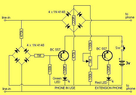
This project has two features. It will let you know when a single phone is using the line and also when two phones are on the line! The green LED indicates the first phone and the red LED indicates...
LEDs lining the headliner will fade in when the door is opened and fade out when the door is closed. The necessary components include a circuit to utilize 12V power from the vehicle to illuminate 15 LEDs and control...
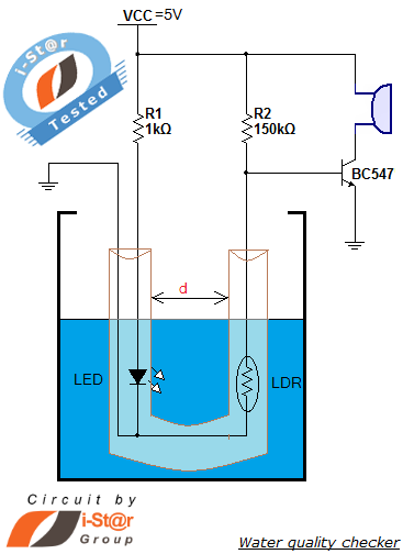
How to measure water purity and test water quality using a simple electronics project. Water purity measurement and water quality analysis can be performed using a water purity checker circuit. This circuit is constructed around a Light Dependent Resistor...
It had been a little over a decade since the invention of the transistor when this article appeared in the August 1959 edition of Popular Electronics. Transistors were still a mystery to many, including engineers, technicians, and hobbyists. Author...