
American Police Car Siren by IC 555

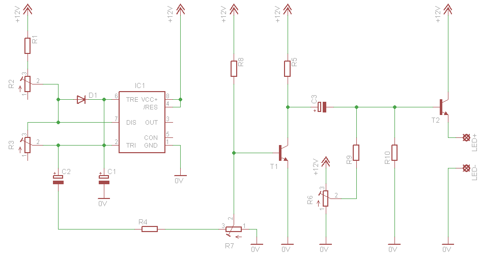
The circuit comprises two 555 timer integrated circuits (ICs), each serving distinct functions to replicate the sound of a police siren. The first timer, positioned on the right, is set up in a monostable mode to produce a square wave tone, which simulates the alarm sound. This timer's output frequency is adjustable, allowing for variations in the siren tone, which is essential for realism.
The second timer, located on the left, operates in astable mode, generating a continuous ramp waveform with a period of approximately 6 seconds. This waveform is crucial for modulating the frequency of the tone produced by the first timer. The modulation creates a more dynamic and realistic siren effect, mimicking the varying pitch heard in actual police sirens.
A transistor is integrated into the circuit to buffer the output from the second timer. This arrangement strengthens the signal, ensuring that it is sufficiently robust to drive a speaker. The use of a transistor not only enhances the output signal but also provides isolation between the timer circuits and the speaker, preventing potential damage to the timers from load variations.
The overall design of the circuit emphasizes simplicity while effectively achieving the desired sound output. The use of common components such as the 555 timer and a transistor makes the circuit accessible for hobbyists and educational purposes, providing a practical example of sound synthesis using basic electronic components.The second circuit simulates the siren of an American police car. It uses two 555 timers in the circuit. The 555 on the right is wired as an alarm tone generator and the second 555 timer on the left is wired as a low frequency astable timer which generates a ramp waveform of about 6 seconds that is buffered by the transistor and again used to freq uency modulate the tone generator. The transistor is used to help strengthen the signal to the speaker 🔗 External reference
Related Circuits
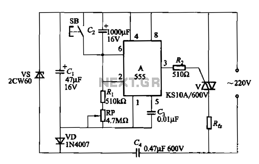
The circuit utilizes a 555 Integrated Circuit (IC) configured as a delay circuit. It transitions from a low to a high state after a button (SB) is pressed, initiating a delay before the output terminal goes high. The output...
This circuit simulates a breathing or pulsing LED using a 555 timer chip. It has gained popularity, receiving numerous comments and emails from users who successfully built the circuit, as well as feedback from those who encountered difficulties when...
An electrocardiogram (ECG), also known as EKG (derived from the German term Elektro-Kardiographie), is an electrical recording of the heart utilized in diagnosing heart disease. This application employs a DrDAQ Data Logger to read and store electrocardiograms. British physiologist...

The circuit facilitates a windshield wiper delay, dynamic braking, and ensures that the windshield wipers return to their resting position. This design prevents the wiper blades from stopping at a location that could obstruct the driver's view. When the...
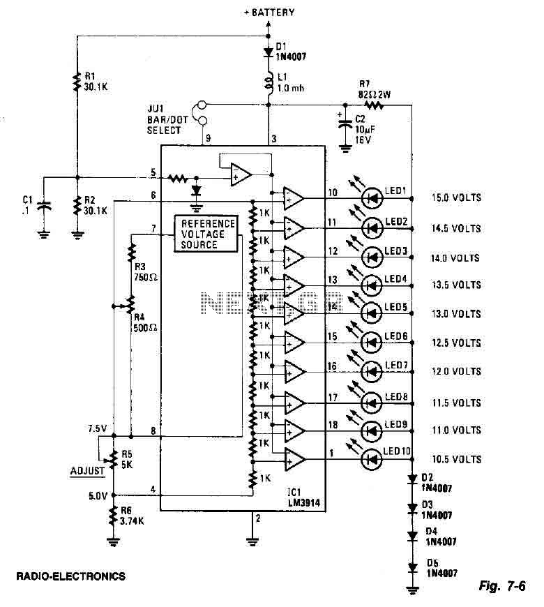
This screen utilizes ten LEDs to indicate a voltage range from 10.5 to 15 volts, with each LED corresponding to a 0.5-volt increment. The core component of the circuit is the LM3914 LED bar graph/display driver. A trimming potentiometer,...
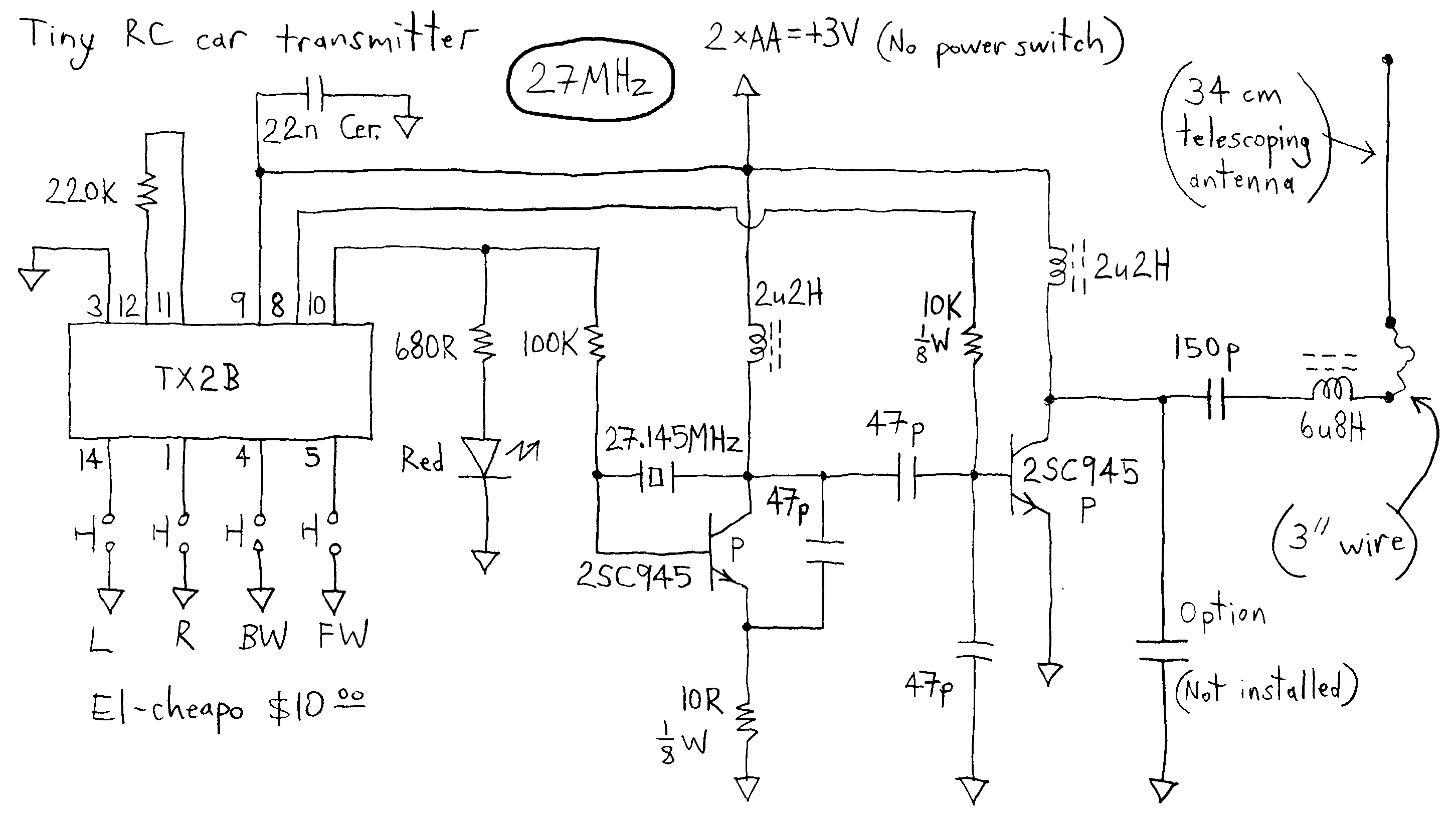
The transmitter runs on only 3V whereas most others run on more voltage. This dirt cheap item uses non-adjustable inductors so it is not possible to tweak for higher output. The common TX2B chip is manufactured by HIGHLAND (SHENZHEN)...