
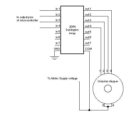
can rotate stepper motor

The circuit design involves using the 4017 decade counter, which is a popular choice for controlling stepper motors due to its ability to sequentially activate outputs based on clock pulses. The Johnson counter configuration allows for efficient management of the bipolar stepper motor's phases, enabling precise control over its rotation.
In this setup, the bipolar stepper motor typically has four phases, which correspond to the four output pins being used from the 4017 IC. The motor phases are energized in a specific order to achieve smooth rotation. The output sequence from the 4017 IC can be arranged to activate pins 3, 2, 4, and 7 in a cyclic manner, effectively stepping the motor through its phases.
To implement this, a clock signal must be provided to the 4017 IC, which can be generated using a 555 timer configured in astable mode or any other suitable clock source. Each pulse from the clock will advance the counter, activating the next output pin in the sequence. This sequential activation will energize the corresponding windings of the bipolar stepper motor, causing it to rotate.
It is essential to ensure that the current ratings of the outputs from the 4017 IC are compatible with the stepper motor driver circuit, as the 4017 itself may not be able to directly drive the motor. A transistor or a dedicated stepper motor driver IC may be required to interface between the 4017 outputs and the motor windings, allowing for higher current handling and protection of the 4017 IC.
Overall, this configuration provides an effective method for controlling a bipolar stepper motor using a Johnson counter 4017 IC, allowing for precise rotational control and the ability to easily adjust the speed and direction of the motor by modifying the clock frequency or the sequence of output activation.I want to rotate stepper motor using jonson counter 4017 IC. I also using bipolar stepper motor. I connected pin 3 2 4 7 (sequence) of 4017ic with.. 🔗 External reference
Related Circuits
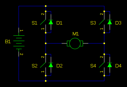
In motor control circuits, precautions must be taken to prevent the motor from feeding back into the power supply, which can cause the supply voltage to rise and potentially damage components. However, unless an external force is accelerating the...
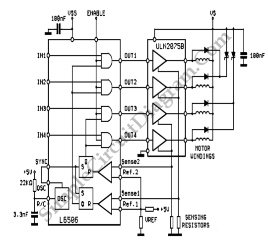
To sense and control the current in stepping motors and other similar devices, a linear integrated circuit such as the L6506 can be utilized. This chip set enables the formation of a constant current output. The L6506 is a versatile...
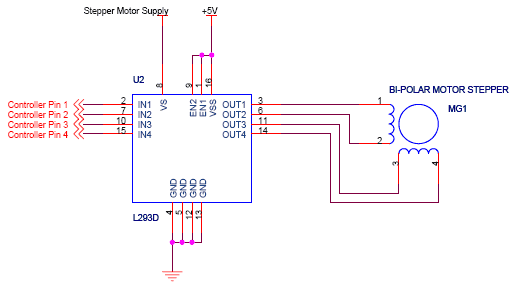
The circuit features four pins labeled "Controller pin 1," "Controller pin 2," "Controller pin 3," and "Controller pin 4," which are responsible for controlling the motion and direction of the stepper motor based on the step sequence programmed into...
Stepper motors, because of their distinct design, can be operated with a high level of precision without the need for feedback mechanisms. The shaft of a stepper motor, equipped with a series of magnets, is governed by a set...
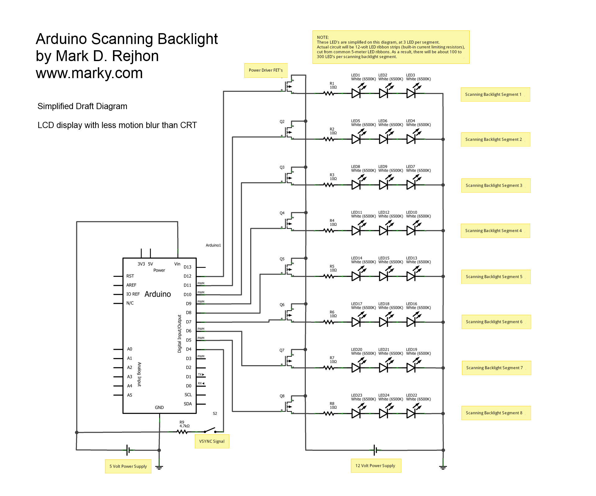
This is a simplified schematic diagram for a homemade scanning backlight driven by an Arduino, an open-source electronics prototyping platform. The Arduino monitors the VSYNC signal (input-lag compensated) and executes a backlight scanning sequence, using ultra-short strobes of super...
A dual benefit for battery-powered portable devices is provided by Class D audio amplifiers. They produce much less power dissipation than their linear counterparts. Class D audio amplifiers, also known as switching amplifiers, are designed to achieve high efficiency and...