
Capacitance meter
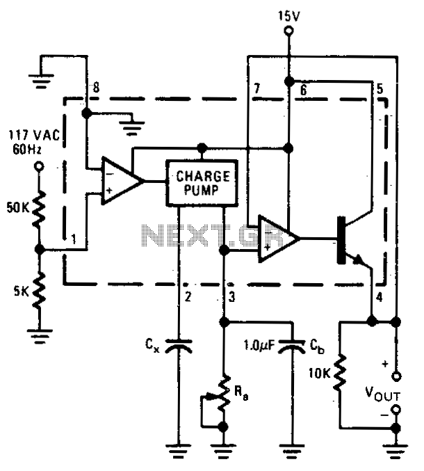
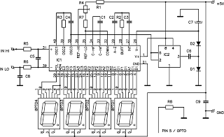
The described circuit utilizes a charge pump configuration to measure capacitance values by translating them into a corresponding output voltage. The charge pump's pin 2 is designated for connecting the capacitor under test, while the output voltage reflects the capacitance value based on a defined relationship. Specifically, as the capacitance increases from 0.1 µF to 0 µF, the output voltage decreases linearly from 1 volt to 0 volts, indicating a direct correlation between capacitance and output voltage.
The circuit is powered by a stable 15-volt power supply, which is essential for maintaining consistent operation across the measurement range. The reference frequency of 60 Hz is critical as it provides a stable timing signal for the charge pump operation, ensuring accurate capacitance measurements. This frequency is typically derived from the mains power supply, which is common in many electronic measurement devices.
The use of a 111 kΩ resistor in the circuit serves as a part of the voltage divider or feedback mechanism, which helps in calibrating the output voltage according to the capacitance range. This resistor value is chosen to optimize the sensitivity and linearity of the output voltage in relation to the capacitance being measured.
Overall, this capacitance measurement circuit is designed for simplicity and effectiveness, making it suitable for various applications in electronics where capacitance needs to be evaluated. Proper implementation of the charge pump and associated components will yield reliable measurements across the specified capacitance range.Output voltage is proportional to the capacitance connected to pin 2 of the charge pump. The meter works over a range of 01 to 0 µF with a set at 111 K. Over this range of capacitance, the output voltage varies from 1 to 0 volts with a 15 volt power supply A constant frequency reference is taken from the 60-Hz line. 🔗 External reference
Related Circuits
A capacitance meter is an essential instrument for electronics hobbyists and professional electronic technicians. A capacitance meter is a specialized device designed to measure the capacitance of capacitors in various electronic circuits. It typically features a digital or analog display...
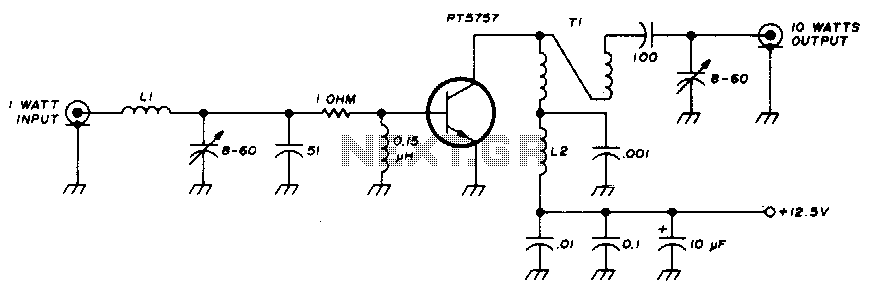
This 10-watt, 144-MHz power amplifier utilizes a TRW PT5757 transistor. The inductor LI consists of 4 turns of no. 20 enameled wire with a 3/32" inner diameter, while inductor L2 comprises 10 turns of no. 20 enameled wire with...
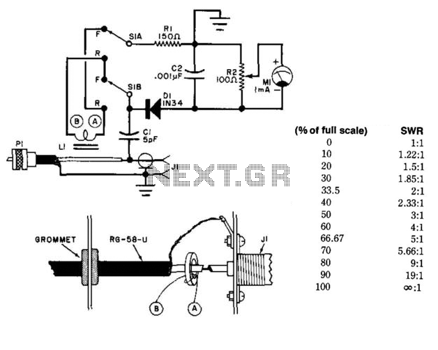
This circuit utilizes a toroidal pickup coil encircling the center conductor of a coaxial cable to measure the SWR (Standing Wave Ratio) of an antenna. The inductor (LI) consists of two turns of #26 enameled wire wound on a...
Measurement of physiological parameters such as heart rate and respiration rate is essential in the medical field. A simple method for measuring respiration rate utilizes a displacement transducer, which is fast and cost-effective. This method allows for the measurement...
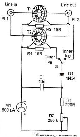
A simple meter is designed to check the balance of currents running in the two legs of a transmission line. This device can evaluate the balance of currents between the inner conductor and the outer coaxial conductor in a...
This circuit is a digital voltmeter with an LED display, ideal for measuring the output voltage of a DC power supply. It features a 3.5-digit LED display with a negative voltage indicator and measures DC voltages from 0 to...
Warning: include(partials/cookie-banner.php): Failed to open stream: Permission denied in /var/www/html/nextgr/view-circuit.php on line 713
Warning: include(): Failed opening 'partials/cookie-banner.php' for inclusion (include_path='.:/usr/share/php') in /var/www/html/nextgr/view-circuit.php on line 713