
Line Bal Test Meter
The Transmission Line Balance Test Meter serves as an essential tool for amateur radio operators, enabling them to assess the balance of currents efficiently. The inclusion of ferrite toroidal cores in the design enhances the sensitivity of the current transformers, allowing for accurate measurements of the currents flowing in both legs of the coaxial line. The rectifier and filter circuit convert the AC signals induced in the transformers into a readable DC output for the micro-ammeter, providing a clear indication of current balance.
This device is particularly beneficial in installations where antennas are connected via coaxial cables, as it helps prevent radiation issues that can arise from unbalanced currents. By routinely checking the balance of currents, operators can ensure that their antenna systems operate efficiently, minimizing interference and optimizing performance. The design's simplicity allows for easy integration into existing setups, making it a practical solution for both novice and experienced amateur radio operators.A simple meter to check the balance of currents running in the two legs of a transmission line. It can be used to check the balance of currents between the inner conductor and the outer coaxial conductor in a coax cable as well as between the legs of an open wire pair. (Originally published in "Amateur Radio", August 2009 - Some errors in the circuit diagram first published are corrected here. The corrected circuit also follows in the September 2009 issue of "Amateur Radio") A typical amateur radio antenna installation makes use of a simple dipole or other balanced form of antenna fed via a coaxial transmission line. Because the line is unbalanced, some form of unbalanced to balanced coupling is normally necessary between the coaxial line and the antenna.
Without this coupling, a condition is set up where currents running in the inner and outer legs of the coax line are unbalanced and a common mode or longitudinal current component is developed along the length of the line, causing radiation from the line. Apart from distorting the radiation pattern inherent to the antenna proper, it encourages annoying induction into equipment and wiring within the radio shack as well as on receiving encouraging induction of vertically polarised near field noise.
A typical balancing interface is the choke balun which must have sufficient common mode rejection impedance to minimise the longitudinal current component. Whilst most radio amateurs possess an SWR meter which can be used in series with the coax line to check how well the antenna is matched to the 50 ohm line, it gives no indication that the currents running in the two legs of the line might be unbalanced.
The SWR meter can show a perfect 1:1 SWR indicating that the antenna is loading the line with a resistance of 50 ohms. However with such a condition indicated there can still be a high longitudinal component flowing and radiation from the line.
Whether there is a serious unbalance of currents in the line legs can easily be checked by measuring the two currents. However it doesn`t seem to be something which is routinely done in checking out the antenna system and verifying whether the coupling interface (such as the choke balun ) is adequate for the job.
To check out balance of line leg currents in such antennas as the EH, I have previously made use of thermo couple RF ammeters, one inserted in series with each leg. I experienced current difference as high as 2 to 1. Such RF meters were commonplace in transmitters of an earlier era but I don`t see them any more as items in our local electronics shops.
Whilst Old Timers like myself still have them, they are probably not too plentiful on the shelves of radio amateurs more recently introduced to amateur radio. Instead It seemed to me that there was a need for a simple test unit to check out the line balance by connecting it in series with the coax line much like one would connect in the SWR meter to check out the line to antenna matching.
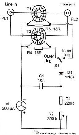
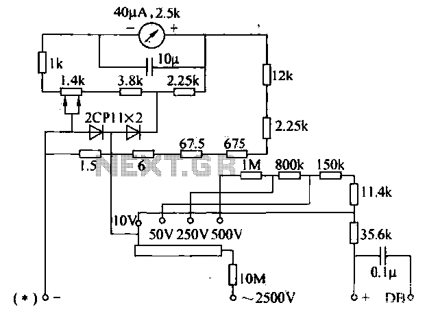
So the Transmission Line Balance Test Meter is born. The circuit diagram is shown in figure 1. All we need is two identical ferrite toroidal cores to make up current transformers, one placed in series with each leg of the coax line. The outputs from secondaries of the two transformers are fed through a selection switch into a rectifier and filter circuit to give a line current indication on a micro-ammeter.
By selecting one, and then the other, of the two positions of the switch, the currents in the two legs of the line can be compared. If near equal, we can be satisfied that the balance is OK. If different, there is a common mode current component on the line and we can expect it to radiate. To get rid of this component, we may have to improve the balancing interface between the line an the antenna.
If a choke balun is used this might mean increasing the inductance of the balun unit. In my unit I used Philips Ferroxcube cores typ 🔗 External reference
Related Circuits
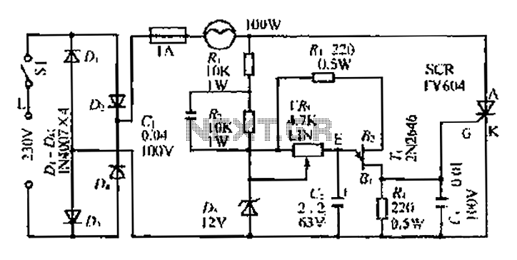
An AC voltage of 30V is rectified. The positive terminal is connected to a fuse and a 100W bulb, while the negative terminal is connected to a thyristor. A Zener diode provides a stable bias voltage. A variable resistor...
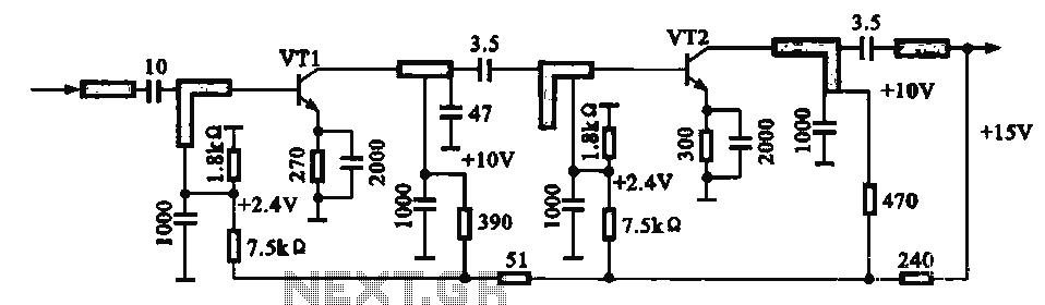
An IF pre-amplifier circuit is presented in a distributed-parameter microstrip configuration. It operates within the frequency range of 950 to 1,470 MHz. The output impedance is approximately 75 ohms. The power supply for the circuit is connected to the...

Signals always involve at least two paths to complete a circuit. For instance, when electrons travel down the center lead of a guitar cable, an equivalent number return on the shield. The shaft of the plug connects to ground...
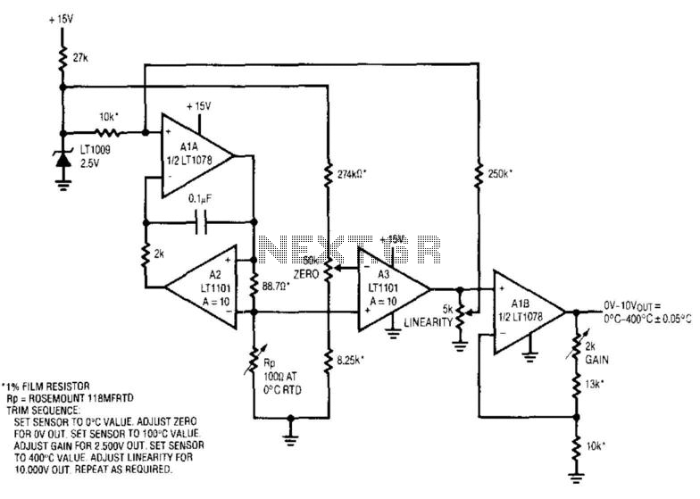
This circuit integrates a current source and a platinum RTD bridge to create a high-accuracy thermometer. The ground-referred RTD is part of a bridge that includes the current drive and the LT1009 biased resistor string. The current drive enables...
The voltage converter can be configured to switch between AC voltage ranges using a selector switch. The measurement circuit is depicted in the accompanying figure. In this configuration, a shunt resistor is placed in parallel with the header, maintaining...
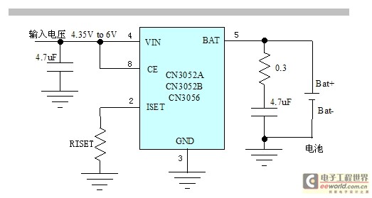
The CN3052A/CN3052B/CN3056 is a high-performance linear lithium battery management chip. It integrates a power transistor, eliminating the need for an external sense resistor and a choke flow diode for current sensing. Only a few peripheral components are required, and...
Warning: include(partials/cookie-banner.php): Failed to open stream: Permission denied in /var/www/html/nextgr/view-circuit.php on line 713
Warning: include(): Failed opening 'partials/cookie-banner.php' for inclusion (include_path='.:/usr/share/php') in /var/www/html/nextgr/view-circuit.php on line 713