
capacitive sensor
The circuit operates on the principle of capacitive sensing, which allows it to detect the presence of a human hand without direct contact. The capacitive sensor behind the banner registers changes in capacitance caused by the proximity of a hand, which is sufficient to trigger the relay. The relay serves as a switch to activate various devices, such as lights or toys, enhancing the visual appeal of the shop window.
The components Q1, Q2, and Q3 are configured in a super-Darlington arrangement, which provides high sensitivity and amplification of the signal from the capacitive sensor. This configuration is particularly advantageous for low-power applications, as it allows the circuit to respond effectively to small changes in capacitance. The use of a high-voltage-rated capacitor in the ground connection is crucial for safety, ensuring the circuit can handle potential surges from the mains supply.
Capacitor C1, along with diodes D2 and D3, is essential for ensuring that the relay switches cleanly without bouncing, which can cause erratic operation. The choice of a wall plug-in transformer for the power supply simplifies the design and enhances safety, as it isolates the circuit from the mains supply and provides a stable voltage output suitable for the relay's operation.
This circuit design presents a versatile solution for retailers looking to engage customers through interactive displays, particularly during high-traffic seasons such as Christmas. By adapting the circuit to different applications, shop owners can create unique experiences that draw attention and encourage purchases.For proper operation, circuit ground must be connected via a small value, high voltage-rating capacitor to one side of the mains supply socket. The "Live" side is the right one. The purpose of this circuit is to animate shop-windows by means of a capacitive sensor placed behind a post-card-like banner.
The card is placed against the glass in side the shop-window, and the visitor can activate the relay placing his hand on the card, from the outside. Especially suited for toy-shops, the circuit can activate model trains, small electric racing cars, lights etc.
Further applications are left at user`s imagination. Adopt it to increase the impact of your shop-window on next Christmas season! Q1, Q2 & Q3 form a high impedance super-Darlington that drives the relay, amplifying the 50Hz alternate mains-supply frequency induced in the sensor by the human body. C1 & D2, D3 ensure a clean relay`s switching. Power supply can be any commercial wall plug-in transformer with rectifier and smoothing capacitor, capable of supplying the voltage and current necessary to power the relay you intend to use.
🔗 External reference
Related Circuits

A modulated current is supplied by the integrated rotational speed sensor KMI 15/x. This current signal needs to be converted into a ground-referenced voltage signal. The KMI 15/x sensor operates by generating a modulated current proportional to the rotational speed of...
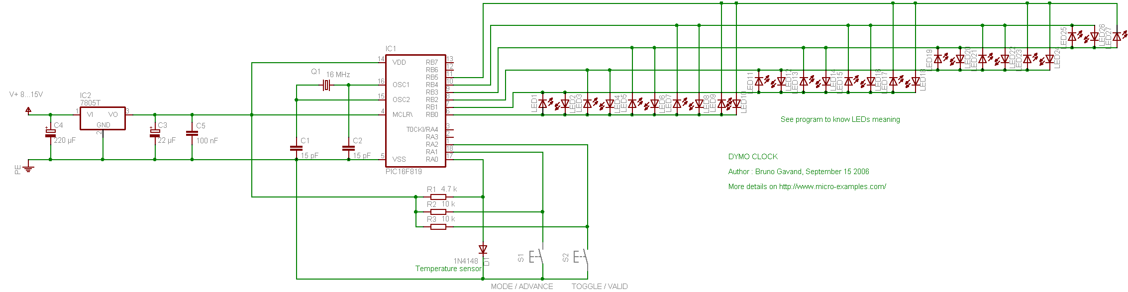
The following circuit illustrates the PIC16F819 Dymoclock Sensor Circuit Diagram. Features include an economical temperature sensor, the use of only LEDs, and the absence of a decoder. The PIC16F819 Dymoclock Sensor Circuit utilizes a PIC16F819 microcontroller, which is a versatile...

This is an affordable method for measuring temperature and humidity with a computer interface, designed as an entry-level project for high school students on a limited budget. The project involves the integration of a temperature and humidity sensor, such as...

This circuit assists in parking a car near a garage wall by providing distance alerts. LED D7 illuminates when the bumper-wall distance is approximately 20 cm. When the distance decreases to about 10 cm, both D7 and D6 illuminate,...

The power switch with an infrared proximity sensor is designed to detect obstructions at distances ranging from a few millimeters to several centimeters. The power switch utilizing an infrared proximity sensor operates on the principle of emitting infrared light and...

This circuit was designed to assist in parking a car near a garage wall while reversing. LED D7 lights up when the distance to the wall is approximately 20 cm. When the distance reduces to about 10 cm, both...
Warning: include(partials/cookie-banner.php): Failed to open stream: Permission denied in /var/www/html/nextgr/view-circuit.php on line 713
Warning: include(): Failed opening 'partials/cookie-banner.php' for inclusion (include_path='.:/usr/share/php') in /var/www/html/nextgr/view-circuit.php on line 713