
Capacitor Box Circuit
The discharging circuit is designed with several critical components that work together to manage high voltage safely and effectively. The four capacitors, each rated at 4 µF, are connected in parallel to achieve a total capacitance of 16 µF, which allows for significant energy storage. The voltage divider is a vital component that ensures the high voltage across the capacitors is safely reduced before being measured by the voltmeter. This is crucial for monitoring the system's status, as the voltmeter's readings directly inform the operator of the charge level, enabling timely and safe discharges.
The three-way switch serves as the primary control interface for the circuit, allowing the user to switch between charging, idle, and discharging modes. In the charging mode, the capacitors are connected to a specialized power supply capable of stepping up 9 V to 4000 V, which is essential for achieving the high voltage necessary for the intended application. The idle position is strategically included to provide a buffer time for preparations, although caution is advised due to the inherent energy leak that occurs in this state.
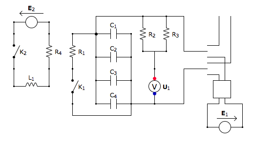
The safety relay circuit, which includes the K1 and K2 switches, is a critical feature that ensures the circuit can be safely discharged when the box is opened. The closure of K1 upon the opening of K2 activates a rapid discharge through the resistor R1, dissipating the stored energy in the capacitors in a controlled manner. This design minimizes the risk of accidental discharge and enhances user safety, especially in high-voltage applications. Overall, the circuit is engineered to provide a comprehensive solution for managing high voltage discharges while prioritizing safety and operational efficiency.This is the discharging circuit: the red lines show the energy of the capacitors flowing to the terminals when the switch is placed up. The circuit is complete because the terminals are connected by Ni-Chrome wire or solder The green part of the circuit is the safety: when the relay is turned off or the relay switch is opened (when the box is open
ed), the K1 switch is closed and the capacitors release all of their energy into the resistor R1. This happens in a matter of milliseconds The untouched schematicIn the center of the circuit. We can see the 4 capacitors in parallel. Each of these has a capacitance of 4 µF and so the 4 parallel capacitors offer a total capacitance of 16 µF. To the right of this, we can see a voltage divider and a voltmeter. This voltmeter is used to measure a voltage across the capacitors, but since these go up to 3500 V on every charge, we have to divide the voltage first.
The voltage divider has a factor of 1/100: when we see 35V on the voltmeter, we know there are 3500 V across the capacitors. This allows us to know how and when the capacitors are charged, so we can take the proper course of action.
This includes discharging what is left of the energy in the capacitors when we want to manipulate the probe, or simply making sure the box is fully discharged when we store it. To the right of that, we see a three way switch, this allows us to control the charging and discharging of the capacitors.
When the switch is down, the capacitors get charged by the power supply at the bottom right of the circuit. This is a black box that transforms 9V into 4000V. The power supply E1 is set to 9V and is outside the box. This way, we only manipulate the 9V wires outside the box, and all of the high voltage is inside the box (at the charging stage).
In the middle position the system is idle: this allows us to have some time to get the camera, strobe, and lights ready for the picture before we discharge. It is unadvisable to stay in the idle position when charged, as there is a noticeable energy leak (on the order of a few hundred volts every 10 seconds).
Finally the switch can be in the discharging position, in which the capacitors are simply connected to the terminals on the upper right, which generate a spark if nichrome wire or solder bits are across the prongs. To the left of the capacitors, we see the safety relay circuit. If switch K2 is to be opened (upon opening of the box), then the inductor L1 looses power and the switch K1 is closed.
This dissipates all of the energy stored in the capacitors thanks to R1. This is an important internal safety feature that safely discharges the capacitors internally in a matter of milliseconds. 🔗 External reference
Related Circuits
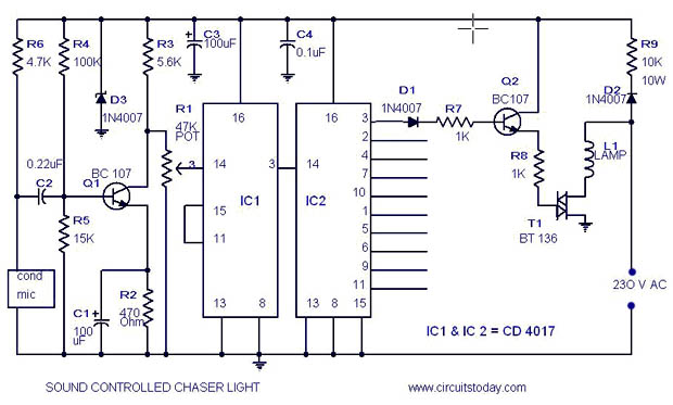
A simple musical light chaser circuit diagram and schematic using IC CD4016. This circuit blinks lights in response to sound, audio, or music output, causing 10 lights to dance according to sound frequency. The musical light chaser circuit utilizing the...
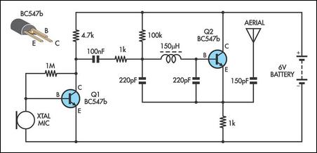
This AM transmitter is designed for simplicity, featuring an untapped inductor with a single winding. The inductor can be easily sourced as a standard RF choke, such as the Jaycar Cat LF-1536. To minimize the circuit size, a conventional...

Q1 is an audio amplifier, and U1 is utilized as a 31.5 kHz subcarrier, which is comparable to the 38 kHz FM multiplex. The pilot frequency is 15.734 kHz. In this circuit, Q1 serves as the audio amplifier, responsible for...
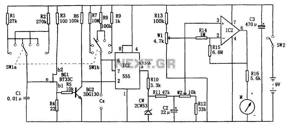
The circuit illustrated in Figure 555 represents a DC capacitor tester. This tester includes a pulse generator, a single-shot circuit, and a head indicating DC amplifier circuit. It is capable of measuring capacitance in the range of nanofarads (nF)...
An RF field indicator is needed to verify power stages and transmitter antennas. This radio field indicator allows for the measurement of radiated energy from antennas. An RF field indicator is a crucial device in the field of telecommunications and...
The circuit was quickly assembled from components available in a home lab and performed well during initial tests using a telephone line simulator and a line connected to a PBX. Reports indicate that this circuit functions effectively in Australia....
Warning: include(partials/cookie-banner.php): Failed to open stream: Permission denied in /var/www/html/nextgr/view-circuit.php on line 713
Warning: include(): Failed opening 'partials/cookie-banner.php' for inclusion (include_path='.:/usr/share/php') in /var/www/html/nextgr/view-circuit.php on line 713