
555 the DC capacitor tester
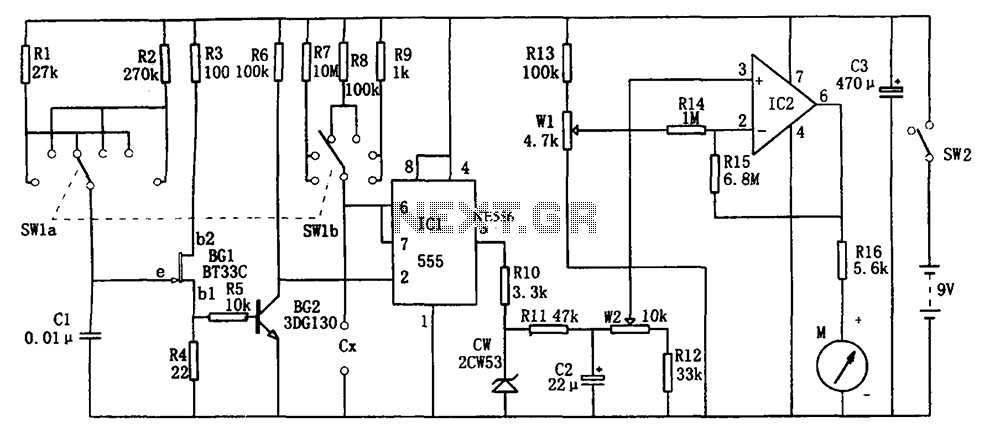
The DC capacitor tester circuit operates by generating a pulse signal through the pulse generator, which is then fed into a single-shot circuit. This circuit is designed to produce a single output pulse in response to the input pulse, effectively allowing for a controlled measurement of the capacitor's characteristics. The head indicating DC amplifier circuit is responsible for amplifying the voltage signal generated by the capacitor under test, enabling accurate readings of its capacitance.
The measurement ranges are defined by the selection of appropriate resistors and capacitors in the circuit, which determine the sensitivity and scale of the measurements. For instance, the lower ranges (0 to 100 pF and 0 to 1 nF) utilize high-precision components to ensure accurate readings of small capacitances, while the higher ranges (0 to 1 μF and 0 to 10 μF) can accommodate larger capacitors, making the tester versatile for various applications.
In practical use, the tester is connected across the terminals of the capacitor to be measured. The resulting voltage signal, once amplified, can be displayed on a digital or analog meter, providing a clear indication of the capacitor's value. This circuit is particularly useful in electronics testing and repair where accurate capacitance measurements are necessary for troubleshooting and component validation. As shown in Figure 555 constituting the DC capacitor tester. The tester from the pulse generator, single-shot, and the head indicating DC amplifier circuit. It measures NpF ~ 1 0 mu F capacitor. Range is divided into 0 ~ 100PF, 0 ~ 1nF, 0 ~ 10nF, 0 ~ 100nF, 0 ~ 1 mu F, 0 ~ 10 mu F.
Related Circuits
It allows car headlights to flash on and off simultaneously or alternately. Components: 555 IC, transistor, resistor, relay, polarized capacitor. The circuit utilizes a 555 integrated circuit (IC) in a monostable or astable configuration to control the flashing of car...
Field-effect transistors (FETs) are integral components found in various applications such as power sections, LCD inverters, uninterruptible power supplies (UPS), amplifiers, monitor B+ circuits, and ATX power supplies. When a FET fails, it is essential to use a meter...
The information apparatus includes a buck rectifier power supply providing Vdd at +12V, a timing circuit, a multivibrator, and the output from the first amplifier. The components R1, RP1, and C3 are used to initiate timing, with the timing...
This continuity tester emits a beep sound when it detects electrical current conduction between its probes. Below is the schematic diagram of this audible device. The continuity tester is a simple yet effective tool used to check the integrity of...

This circuit is designed to detect the approximate percentage of salt contained in a liquid. After careful calibration, it provides a quick, rough indication of the salt content in liquid foods for dietary purposes. The circuit utilizes the LM324...
The UTP Cable Tester is designed for multiple applications, primarily to test UTP network cables. It can also assist in identifying the correct cable from a large bundle of similar cables. The circuit can be adapted to test any...
Warning: include(partials/cookie-banner.php): Failed to open stream: Permission denied in /var/www/html/nextgr/view-circuit.php on line 713
Warning: include(): Failed opening 'partials/cookie-banner.php' for inclusion (include_path='.:/usr/share/php') in /var/www/html/nextgr/view-circuit.php on line 713