
Capacitor Charger Lead Acid Battery
The protective circuit is composed of Ty1 thyristor, diodes D2 and D3, resistor R2 and capacitor C4. Increases when the voltage across the secondary winding 18, and closes the thyristor short-circuits it. Slight overshoot will cause the thyristor immediately closed again. During the positive half-wave and closes several times, see Figure 2. If the output is connected to the battery protection circuit does not apply, because a positive voltage on the secondary side does not exceed 15 V. The charger is used only one-way rectifier. It's not just for saving money and parts. As already mentioned the phenomenon of resonant charger works with one-way rectifier better - less charging current changes with the change of output voltage.
The fuse protects the output of the charger in case of wrong connection (polarity) of the battery. LEDs indicate a broken fuse. Instead of LEDs, R4 and D4 can use a small light bulb 12 / 0.05 or 0.1 A.
The output meter is connected to a switch that can measure the charging current or battery voltage. Depending on the gauge is to be properly selected resistor R3 and the trimmer P1 and P2.
In the original charger, I used the PR1 site switch from the old stove. He is in position 1 involved a series of heating coils in position 2, joined a heating coil in position 3 involves two parallel spirals. Place the plates on the stove, I switch involves two capacitors 4 uF. So I could choose one of three charging currents using two capacitors. If such a switch somewhere rake, definitely use it.
I built a charger for more than 15 years ago during the military service, along with the 'comrades' EA, which has been undertaken mechanical design for our master. Until now, I only stayed Appliance. Parts:
R1 220 kOhm
R2 100 Ohm
R3 0.1 Ohm, see text
R4 680 Ohm
P1, P2 see text
C1 2 uF (2.2 uF), 275 VAC (600 VDC)
C2 4 uF (3.9 to 4.7 uF), 275 VAC (600 VDC)
C3 6 uF (5.6 to 6.8 uF), 275 VAC (600 VDC)
D1 KY708 (10 A/100 V)
D2 16 V Zener diode
D3 1N4007 (KY132)
D4 1N4148, 1N4007
Ty1 TIC106 or similar
LED Any red 20 mA
PR1 double four-position for the voltage of 250 V and current of 3 A
PR2 double dip
Tr 10:1 (230 / 22 V) 50 - 100 VA or series produced by / or Manufacturing usual 230/24 V
Dt glow neon lights
After FUSE / FUSE 6.3A
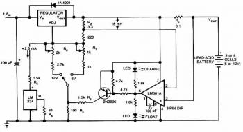
The described capacitor charger circuit employs a resonant charging method, which is efficient due to the limited heating of components. The primary side of the transformer features a series arrangement of capacitors (C1, C2, C3) that limits the charging current through the primary winding, while the transformer itself provides isolation and steps up the voltage on the secondary side to approximately ten times the primary voltage.
The output stage utilizes a single diode (D1) for rectification, which simplifies the design and enhances performance by reducing fluctuations in charging current. A protective circuit is integrated to safeguard against high voltage spikes when the output is not connected to a load. This circuit employs a thyristor (Ty1) that activates at a critical voltage threshold, effectively short-circuiting the secondary winding to prevent damage.
The output is equipped with a fuse to protect against reverse polarity connections and a visual indicator (LED) to signal fuse status. An output meter, connected via a switch, allows for the measurement of either charging current or battery voltage, with adjustable resistors (R3) and trimmers (P1, P2) to calibrate the readings based on the selected gauge.
The design also incorporates a multi-position switch (PR1) to select different charging currents by utilizing various combinations of capacitors, providing versatility in charging applications. Overall, this charger design is suitable for a range of battery charging tasks, balancing efficiency, safety, and functionality.Leaving aside the complex chargers, "stuffed" electronics capacitor charger is one of the best connections. Charging current is limited by the resistor (or other element of the changing excess energy into heat), but the reactance of the capacitor to the primary side.
The charger is not heated, the greatest loss occurs only at the transformer and rectifier diode. Connecting the charger is in the picture 1 . On the primary side switch is transformátru P?1a, which we include in series with the primary winding of the transformer capacitors C1 to C3. Capacitors its reactance to limit current through the primary winding. B ecause the transformer has a conversion ratio of about 10:1, is transformed on the secondary side current of about 10 times larger. Transformers also provide galvanic isolation from the mains charger output. P?1b switch only serves to connect the neon indicator. On the secondary side will be sufficient in the case nejjednduím rectifier diode D1. Here, the circuit is completed with a protective circuit and gauge output current and voltage. The capacitor charger is unfortunately one major vice. Output terminals can easily be shorted, but may not be unconnected to the load. The primary winding of the transformer is with limiting capacitor form a resonant circuit that may nakmitat much higher voltage than the voltage.
Then we have two choices - either we can use capacitors and transformers to "withstand" voltage to 2 kV, and we must never let unconnected output when the charger is enabled. Here, the connection uses capacitors and transformers for standard voltage, it is accompanied by a protective circuit which short-circuits the secondary winding of the transformer is not connected to any load.
The protective circuit is composed of Ty1 thyristor, diodes D2 and D3, resistor R2 and capacitor C4. Increases when the voltage across the secondary winding 18, and closes the thyristor short-circuits it. Slight overshoot will cause the thyristor immediately closed again. During the positive half-wave and closes several times, see Figure 2 . If the output is connected to the battery protection circuit does not apply, because a positive voltage on the secondary side does not exceed 15 V.
The charger is used only one-way rectifier. It's not just for saving money and parts. As already mentioned the phenomenon of resonant charger works with one-way rectifier better - less charging current changes with the change of output voltage. The fuse protects the output of the charger in case of wrong connection (polarity) of the battery. LEDs indicate a broken fuse. Instead of LEDs, R4 and D4 can use a small light bulb 12 / 0.05 or 0.1 A. The output meter is connected to a switch that can measure the charging current or battery voltage. Depending on the gauge is to be properly selected resistor R3 and the trimmer P1 and P2. In the original charger, I used the PR1 site switch from the old stove. He is in position 1 involved a series of heating coils in position 2, joined a heating coil in position 3 involves two parallel spirals.
Place the plates on the stove, I switch involves two capacitors 4 uF. So I could choose one of three charging currents using two capacitors. If such a switch somewhere rake, definitely use it. I built a charger for more than 15 years ago during the military service, along with the 'comrades' EA, which has been undertaken mechanical design for our master. Until now, I only stayed Appliance. Parts: R1 220 kOhm R2 100 Ohm R3 0,1 Ohm, see text R4 680 Ohm P1, P2 see text C1 2 uF (2.2 uF), 275 VAC (600 VDC) C2 4 uF (3.9 to 4.7 uF), 275 VAC (600 VDC) C3 6 uF (5.6 to 6.8 uF), 275 VAC (600 VDC) D1 KY708 (10 A/100 V) D2 16 V Zener diode D3 1N4007 (KY132) D4 1N4148, 1N4007 Ty1 TIC106 or similar Or Similar LED Any red 20 mA Red 20 mA PR1 double four-position for the voltage of 250 V and current of 3 A double-pole, 4-position switch PR2 double dip double-pole, double-throw switch Tr 10:1 (230 / 22 V) 50 - 100 VA or series produced by / or Manufacturing usual 230/24 V Dt glow neon lights After FUSE / FUSE 6.3A
🔗 External reference
Related Circuits
This is a NiMH battery charger using the IC LTC4060, which is powerful, effective, and efficient. The LTC4060 IC specializes in NiMH battery charging, ensuring safe operation with features such as battery temperature protection during charging. It includes a...
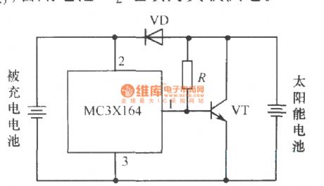
The following circuit illustrates a current-limited solar battery charger circuit diagram. This lead-acid or Ni-Cd battery charger circuit diagram utilizes solar energy to charge a 6-volt, 4.5 Ah rechargeable battery for various applications. It represents a straightforward solar battery...
This circuit provides an initial voltage of 2.5V per cell to quickly charge a car battery. The charging current decreases as the battery charges, and when the current drops to 180 mA, the charging circuit reduces the output voltage...
Almost all 24V power systems in trucks, 4WDs, RVs, boats, etc., utilize two series-connected 12V lead-acid batteries. The charging system can only sustain the total voltage of the individual batteries. If one battery is failing, this circuit will illuminate...
This circuit provides an initial voltage of 2.5 V per cell at 25°C to quickly charge the battery. As the battery charges, the charging current decreases, and when it drops to 180 mA, the charging circuit reduces the output...
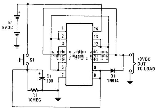
This battery saver circuit can automatically turn off a small piece of test equipment after a desired period of time, allowing for worry-free operation in a workshop environment. The circuit utilizes a CD4011 integrated circuit (IC) to function as...