
solar charger circuit diagram

The current-limited solar battery charger circuit is designed to efficiently harness solar energy for charging a 6V lead-acid or Ni-Cd battery, typically rated at 4.5 Ah. This circuit is particularly beneficial for off-grid applications, where solar energy can be used to power devices without relying on traditional power sources.
The schematic typically includes a solar panel, which converts sunlight into electrical energy, and a charge controller, which regulates the voltage and current flowing to the battery. The charge controller is crucial in preventing overcharging, which can damage the battery and reduce its lifespan. The circuit may also include a blocking diode to prevent reverse current flow from the battery to the solar panel during low-light conditions, ensuring that the battery remains charged even when the solar panel is not generating power.
In addition to the solar panel and charge controller, the circuit may feature a voltage regulator to maintain a steady output voltage, ensuring compatibility with the battery's charging requirements. The entire system can be housed in a weatherproof enclosure to protect the components from environmental factors, making it suitable for outdoor use.
The simplicity of this solar battery charger circuit makes it an excellent choice for hobbyists and professionals alike, providing a reliable solution for charging batteries in various applications, from powering small electronic devices to providing backup power in remote locations.The following circuit shows about Current Limited Solar Battery Charger Circuit Diagram. This Lead Acid or Ni-Cd Battery Charger Circuit Diagram utilizes solar energy to charge a 6 volt 4. 5 Ah rechargeable battery for various applications. This is a great a simple Solar Battery Charger circuit. The most simple power systems Solar Powered Battery Charger Circuit Diagram. solar cell NiCad charger electric circuit diagram. which is very useful for electronic devices at home or in your vehicle. When connecting a solar panel to a rechargeable battery, it is usually necessary to use a charge controller circuit to prevent the battery from overcharging. When connecting a solar panel to a rechargeable battery, it is usually necessary to use a charge controller circuit to prevent the battery from overcharging.
🔗 External reference
Related Circuits
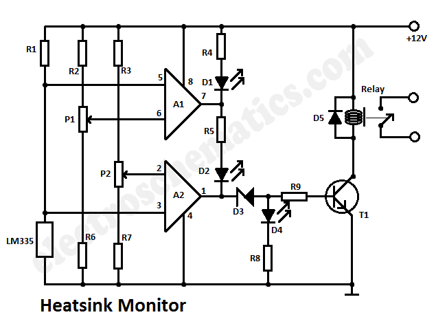
This heatsink temperature monitor circuit uses three LEDs to signal when the temperature exceeds two boundary levels. When the heatsink temperature is below 50 degrees... This heatsink temperature monitor circuit is designed to provide visual indications of temperature levels using...
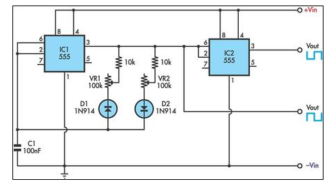
This circuit allows for the independent variation of the on/off times of a 555 timer across a wide range. This capability is not achievable with a conventional 555 timer circuit. The described circuit enhances the functionality of the standard 555...
This audio limiter circuit is simple to construct and is compatible with BA741 operational amplifiers, whether in 8-pin or 4-pin configurations. It requires a symmetrical power supply. The circuit is designed to manage audio input levels effectively. The audio limiter...
A 12-volt relay is connected between two stages such that when it receives 12 volts from the supply, it activates and disconnects the 3-volt DC supply from the melody circuit. Conversely, when mains power is absent, the relay switches...
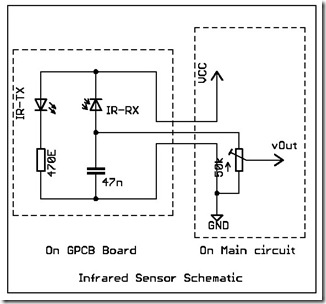
The following circuit illustrates a simple infrared sensor module circuit diagram. Features include a simple infrared sensor module and flame detection. The simple infrared sensor module circuit operates by utilizing an infrared (IR) transmitter and receiver pair. The IR transmitter...
The device utilizes body heat to identify and track its human operator. Central to its heat-seeking function is the Devantech TPA81 Thermal Sensor Array, which features an array of eight horizontally mounted detectors. Each detector is capable of sensing...