
Lead-Acid Battery Charger Circuit
This circuit is designed for efficient battery charging, utilizing a controlled voltage and current management system to optimize battery health and longevity. The initial charging voltage of 2.5V per cell is suitable for rapid charging, ensuring that the battery receives adequate power to reach a full charge efficiently. The transition to a lower float voltage of 2.35V per cell serves as a protective measure against overcharging, which can lead to battery damage and reduced lifespan.
The LM301A comparator plays a crucial role in monitoring the charging process. By comparing the voltage drop across R1 with a predetermined reference voltage, it ensures that the output voltage is adjusted appropriately based on the battery's state of charge. The use of R2 to set the reference voltage at 18 mV is critical for accurate operation, allowing the circuit to respond dynamically to changes in the charging current.
Incorporating temperature compensation through the LM334 temperature sensor is essential for maintaining optimal charging conditions. The placement of the sensor near the battery ensures accurate readings of the battery temperature, allowing the circuit to adjust the charging parameters accordingly. Modifying R5 to 30 ohms for low-temperature operation helps maintain the desired charge characteristics, safeguarding against potential overcharging in colder environments.
The input voltage requirements necessitate that the charger operates with a filtered DC supply that exceeds the maximum output voltage by at least 3V. This design consideration is vital for ensuring stable operation of the voltage regulator. The selection of the appropriate voltage regulator—LM371, LM350, or LM338—based on the maximum current requirements provides flexibility in application, allowing for different battery capacities and charging needs.
Finally, the adjustment of resistors R7 and R8 at specified conditions ensures that the output voltages are accurately set for optimal performance. This level of control and customization makes the circuit adaptable to various charging scenarios, enhancing its utility in automotive battery maintenance and management.This circuit delivers an initial voltage of 2. 5V per cell to rapidly charge a car battery. The charging current decreases as the battery charges and when the current drops to 180 mA the charging circuit reduces the output voltage to 2. 35 V per cell, leaving the battery in a fully charged state. This lower voltage prevents the battery from overchar ching, which will shorten its life. The LM301A compares the voltage drop across R1 with a 18 mV reference set by R2. The comparator`s output controls the voltage regulator, and produce the lower float voltage when the battery-charging current, passing through R1, drops bellow 180 mA. Temperature compensation helps prevent overcharging, the LM334 temperature sensor should be placed near or on the battery.
Because batteries need more compensation at lower temperatures, change R5 to 30 © for a tc of -5mV/0C per cell il this circuit will be used at temperatures below 200C. The charger`s input voltage must be filtered dc that is at least 3V higher than the maximum required output voltage.
Choose a regulator for the maximum current needed: LM371 for 2A, LM350 for 4A, LM338 for 8A. At 250C and with no load, adjust R7 for a Vout of 7. 05V, and adjust R8 for a Vout of 14. 1V. 🔗 External reference
Related Circuits
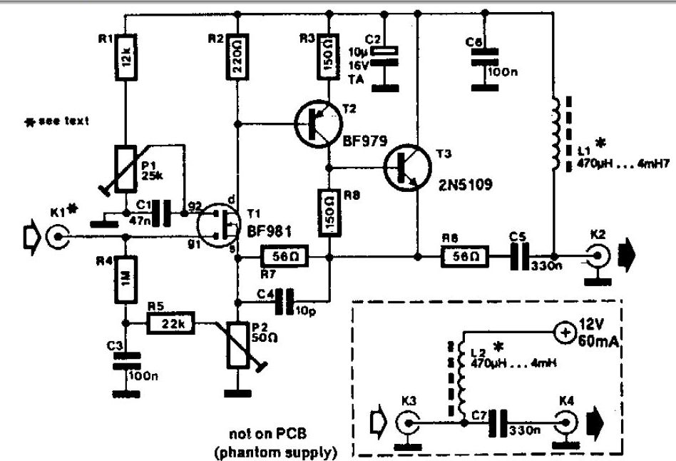
A whip antenna measuring between 30 to 50 cm is capable of receiving signals from 10 MHz to over 220 MHz. The circuit incorporates a BF981 dual-gate MOSFET (T1), which offers low noise characteristics, high input impedance, and enhanced performance. The...
This quartz crystal oscillator circuit exhibits greater stability compared to a parallel resonance circuit. It is capable of generating frequencies up to 30 MHz or even higher when utilizing BFR91 transistors for T1 and T2, along with reduced values...
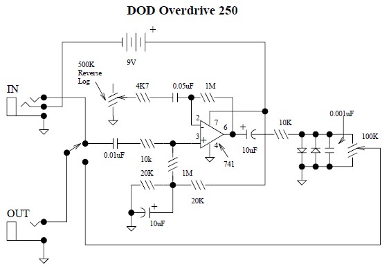
This document provides a circuit diagram for the DOD Overdrive 250 preamp. The DOD Overdrive 250 is similar to the MXR Distortion Plus and several other devices, utilizing a 741 operational amplifier with two diodes on the output channel....
This circuit enables audio monitoring of a remote location, functioning as both a room monitor and a baby alarm. It can be powered by a 12-volt battery or a mains power supply. The interconnection utilizes three wires, allowing for...
The circuit was constructed on a Vero board and tested with a large electrolytic capacitor in place of a battery. A 500-ohm preset resistor determines the output voltage, while a 47k preset resistor regulates the hysteresis and establishes the...
This circuit is a 73 MHz halogen lamp radio-controlled system. Its purpose is to control the power state of a halogen lamp using a remote control. When the push button on the remote control is pressed, the power state...