
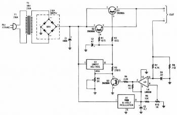
lead acid battery charger schematic
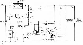
The circuit operates as a battery charger with a focus on maintaining battery health through controlled charging parameters. The initial voltage of 2.5 V per cell is ideal for rapid charging, and the transition to a float voltage of 2.35 V per cell is critical for maintaining battery capacity without risk of damage. The LM301A comparator plays a vital role in monitoring the charging current, ensuring that the circuit responds dynamically to changes in battery state. The design incorporates resistors R1, R2, R3, and R4 to establish voltage references and current thresholds, while R1 specifically acts as a sensing resistor to monitor the charging current.
The inclusion of temperature compensation via the LM334 temperature sensor is essential for maintaining optimal charging conditions across varying environmental temperatures. The adjustment of R5 provides a means to calibrate the circuit for specific temperature ranges, ensuring consistent performance and battery safety.
The selection of voltage regulators (LM371, LM350, and LM338) allows the circuit to adapt to different current requirements, making it versatile for various battery sizes and types. The requirement for a filtered DC input voltage that exceeds the maximum output voltage by 3 V ensures reliable operation and stability of the charging process.
LED indicators provide immediate visual feedback regarding the circuit's status, enhancing user experience and safety. Overall, this circuit design emphasizes efficiency, safety, and adaptability, making it suitable for various battery charging applications.This circuit gives an initial voltage of 2. 5 V per cell at 25ƒ to rapidly charge the battery. The charging current decreases as the battery is charging, and when the current drops to 180 mA, the charging circuit reduces the output voltage of 2. 35 V per cell, leaving the battery in a fully charged state. This lower voltage prevents the battery fr om overcharging, which would shorten its life. The LM301A compares the voltage drop across R1 with an 18 mV reference set by R2. The comparator`s output controls the voltage regulator, forcing it to produce the lower float voltage when the battery-charging current, passing through R1, drops below 180 mA. The 150 mV difference in between the charge and float voltages is certainly set by the ratio of R3 to R4.
The LEDs present the state of the circuit. Temperature compensation assists stop overcharging, especially when a battery goes through wide temperature changes whilst becoming charged. The LM334 temperature sensor ought to be placed near or on the battery to lower the charging voltage by 4 mV/ƒ for each cell.
Because batteries require far more temperature compensation at lower temperatures, alter R5 to 30 © for a tc of -5 mV/ƒ per cell if application will see temperatures beneath -20ƒ. The charger`s input voltage need to be filtered dc that`s at the very least 3 V greater than the maximum required output voltage: approximately 2.
5 V per cell. Choose a regulator for the highest possible current required: LM371 for 2 A, LM350 for 4 A, or LM338 for 8 A. At 25ƒ and with no output load, adjust R7 for a VOUT of 7. 05 V, and adjust R8 for a VOUT of 14. 1V. 🔗 External reference
Related Circuits
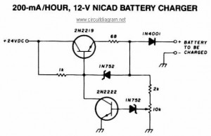
This NiCAD battery charger circuit charges the battery at 75 mA until it is fully charged, after which it reduces the current to a trickle rate. It can completely recharge a dead or unpowered battery in 4 hours, and...
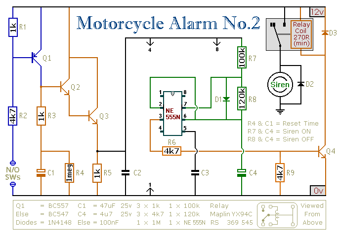
This circuit features an intermittent siren output and automatic reset. It can be operated manually using a key-switch or a hidden switch; but it can also be wired to set itself automatically when you turn-off the ignition. By adding...
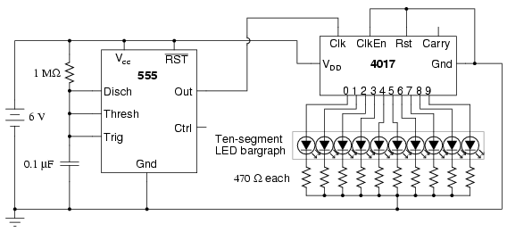
The following circuit illustrates a schematic diagram of an LED sequencer. This circuit is based on the 555 timer integrated circuit (IC). Features include a 555 timer circuit designed to debounce a mechanical switch, a 555 timer circuit to...
The charger's output voltage is adjustable and regulated, featuring an adjustable constant-current charging circuit that is compatible with most NiCad batteries. It is capable of charging a single cell or multiple series-connected cells with a maximum voltage of 18V....
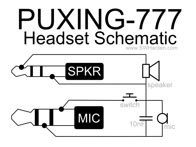
A speaker, microphone, and transmit button circuit designed for the Puxing 777 radio, which is likely compatible with all Puxing radios. The circuit was reverse-engineered from an earphone/microphone headset that originally accompanied the radio to understand its functionality. The...
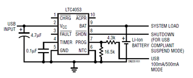
The schematic presented illustrates a minimal component solution for a USB battery charger utilizing the LTC4053 integrated circuit (IC) to create a fully compliant USB charger. This IC functions as a standalone linear charger designed for lithium-ion (Li-ion) batteries,...