
Car Alarm and Immobilizer

The circuit operates by integrating several key components that work collaboratively to provide a comprehensive vehicle security solution. The primary control mechanism is the switch Sw1, which initiates the alarm system. Upon activation, the system enters a delay mode, allowing the user to exit the vehicle. The exit delay is adjustable through resistor R1 and capacitor C1, which define the timing characteristics. The entry delay, similarly adjustable via resistor R9 and capacitor C4, ensures that the user has adequate time to disarm the system upon returning.
The alarm system features an instant alarm zone, which can be activated by additional normally-open switches placed at strategic locations, such as the bonnet or doors. This zone operates independently of the exit and entry delays and provides immediate notification if unauthorized access is attempted. The intermittent siren output, controlled by C6 and R10, serves to deter intruders by producing a loud sound that varies in intensity.
In terms of power management, the circuit requires careful consideration of the fuse placement to prevent damage to the wiring. The choice of siren is also critical; an electronic siren is preferred for its reliability and power consumption characteristics. If the vehicle's horn is utilized, a relay must be employed to ensure that the alarm can handle the higher current demands.
Environmental protection is paramount; therefore, the circuit board and switches should be housed in a weather-resistant enclosure to prevent moisture ingress. The grounding system is flexible, allowing for either a chassis ground or a separate return wire, depending on installation requirements.
Overall, the design emphasizes reliability, user-friendliness, and adaptability to different vehicle configurations, making it a robust solution for vehicle security.This circuit features exit and entry delays, an instant alarm zone, an intermittent siren output and automatic reset. By adding external relays you can immobilize the vehicle and flash the lights. The alarm is "set" by opening Sw1. It can be any small 1-amp single-pole change-over switch - but for added security you could use a key-switch.
Once Sw1 is opened you have about 10 to 15 seconds to get out of the vehicle and close the door behind you. When you return and open the door the buzzer will sound. You have 10 to 15 seconds to move Sw1 to the "off" position. If you fail to do so, the siren will sound. The output to the siren is intermittent - it switches on and off. The speed at which it switches on and off is set by C6 and R10. While any trigger-switch remains closed, the siren will continue to sound. About 2 to 3 minutes after all of the switches have been opened, the circuit will reset. One of the inputs is connected to the vehicle`s existing door-switches. This provides the necessary exit and entry delays. It`s usually sufficient to connect a SINGLE wire to just ONE of the door switches - they`re generally all connected in parallel with the return through the chassis. You can add extra normally-open switches to the door-circuit if you wish; but note that any additional switches will have to be able to carry the current required by your vehicle`s interior light.
Any number of normally-open switches may be connected - in parallel - to the "Instant" input. Since they don`t have to carry the current for the interior light, you can use any type of switch you like. You may want an instant alarm on the bonnet, the boot, the rear-hatch, the rear-doors etc. It doesn`t matter if these already have switches connected to the door-circuit. Simply fit a second switch and connect it to the instant input. It will override the delay circuit. You can use the chassis for the return. However, a ground terminal is provided if - for any reason - you need to run a separate return wire for either zone.
If you`re not using the instant zone then leave out Q2, R3, R4, R5 & D3. The exit delay is set by R1 & C1, the entry delay by R9 & C4, and the reset time by R7 & C3. The precise length of any time period depends on the characteristics of the actual components used - especially the tolerance of the capacitors and the exact switching points of the Cmos Gates. However, for this type of application really accurate time periods are unnecessary. The circuit board and switches must be protected from the elements. Dampness or condensation will cause malfunction. Fit a 1-amp in-line fuse AS CLOSE AS POSSIBLE to your power source. This is VERY IMPORTANT. The fuse is there to protect the wiring - not the alarm. Exactly how the system is fitted will depend on the make of your particular vehicle. Consequently, I CANNOT give any further advice on installation. The circuit is designed to use an electronic Siren drawing 300 to 400mA. It`s not usually a good idea to use the vehicle`s own Horn because it can be easily located and disconnected.
However, if you choose to use the Horn, remember that the alarm relay is too small to carry the necessary current. Connect the coil of a suitably rated relay to the "Siren" output. This can then be used to sound the Horn, flash the lights etc. Before fitting this immobilizer to your vehicle, carefully consider both the safety implications of its possible failure - and the legal consequences of installing a device that could cause an accident.
If YOU decide to proceed, you will need to use the highest standard of materials and workmanship. Remember that the relay MUST be large enough to handle the current required by your ignition system. Choose one specifically designed for automobiles - it will be protected against the elements and will give the best long-term reliability. You don`t want it to let you down on a cold wet night - or worse still - in fast moving 🔗 External reference
Related Circuits
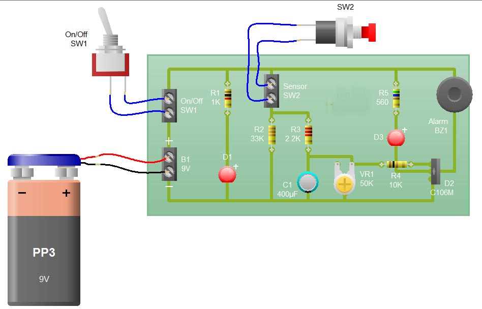
When the sensor switch SW2 is pressed, the LED D3 and the alarm are activated for a certain duration. The timing of the circuit is determined by the resistor R3 and capacitor C1. Additional details regarding the RC circuit...
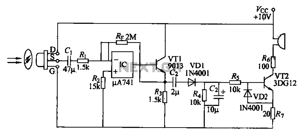
A simple burglar alarm circuit utilizes a pyroelectric sensor (IRA-E100SZI). When human movement is detected, it triggers an electric buzzer alarm. The sensor receives signals through an AC amplifier, which is then converted by a rectifier circuit into a...
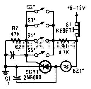
Four parallel switches are employed to monitor four positions. When any switch is closed, SCR1 is triggered, activating the alarm. The alarm is designed to be of the non-interrupting type. The circuit consists of four parallel switches, each representing a...
This microphone circuit was submitted by Lazar Pancic from Yugoslavia. The sound card for a PC typically features a microphone input, speaker output, and occasionally line inputs and outputs. The microphone input is designed specifically for dynamic microphones with...
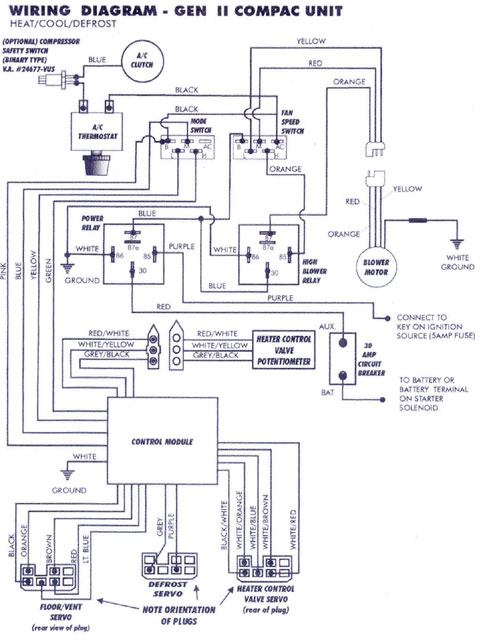
Mercury, Oldsmobile, Plymouth, Pontiac, muscle cars, and antique classic car wiring diagrams are continuously being added to this site. The wiring diagram for the Porsche 911L engine from the 1968 model has undergone changes since the original scheme. For...
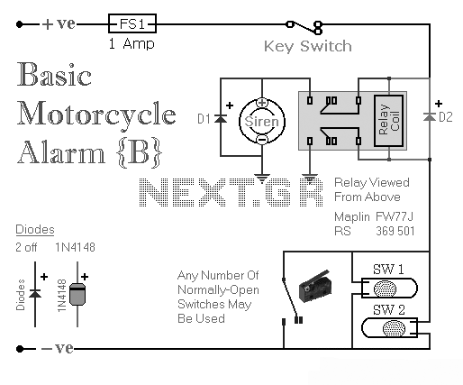
Two simple relay-based motorcycle alarm circuits. These are easy to build and can be used to protect motorcycles, but they also have many other applications. If relays with 6-volt coils are used... The motorcycle alarm circuits described consist of two...