
Parallel Loop Alarm Circuit
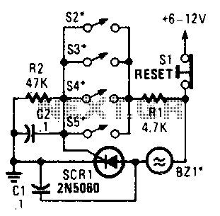
The circuit consists of four parallel switches, each representing a distinct monitored position. The configuration allows for redundancy; if any one of the switches is closed, it completes the circuit, leading to the triggering of the silicon-controlled rectifier (SCR1). This SCR acts as a control element that allows current to flow through the alarm system once it is activated.
The alarm system is specifically designed to be non-interrupting, which means that once it is triggered, it will continuously sound until the condition is manually reset or resolved, rather than turning off automatically after a certain period or upon the release of the switch. This feature is crucial in applications where persistent alerting is necessary to ensure that the monitored condition receives immediate attention.
In terms of implementation, the four switches should be connected in parallel to the anode of SCR1, while the cathode is connected to ground. A resistor may be included in series with the alarm to limit the current and protect the circuit components. Additionally, a capacitor can be added across the SCR to manage the turn-off characteristics and prevent false triggering due to transient signals.
The overall design must ensure that the alarm is powered by a stable voltage source, and appropriate ratings for the switches and SCR should be selected based on the expected load and operational environment. Proper isolation techniques and protective components, such as diodes, may also be integrated to safeguard the circuit against voltage spikes and ensure reliable operation. Four parallel switches are used to monitor four positions. When a closure occurs on any switch, SCR1 triggers, which sounds the alarm. The alarm should be of the noninterrupting type. 🔗 External reference
Related Circuits

This circuit is tested and functional. The LM389 integrated circuit serves as the core element, where the voice channel number is acquired by the microphone (MIC) and converted into electrical signals. These signals are amplified by the volume control...
This timer is designed primarily to turn off a portable radio after a set duration. This feature allows users to relax on the beach or in a hammock, confident that the device will automatically power down after a specified...
Many friends have requested an automatic on/off LED circuit or an LED flashing circuit. This post presents an astable multivibrator circuit designed for LED flashing. It is a simple astable multivibrator circuit utilizing two LEDs (specifically red LEDs) and...

A circuit diagram illustrating the reliability of crystal startup, with power consumption significantly lower than the maximum allowed for the crystal. The transistor Q1 can be one of the following: 2N918, 2N3564, 2N5770, BF180, or BF200. The inductor L1...
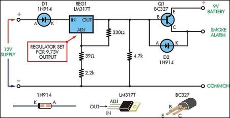
Although smoke alarms are relatively inexpensive devices, the cost of 9V batteries can quickly surpass their initial purchase price. Additionally, the annoyance of intermittent beeping from the alarm as the battery nears the end of its life can be...
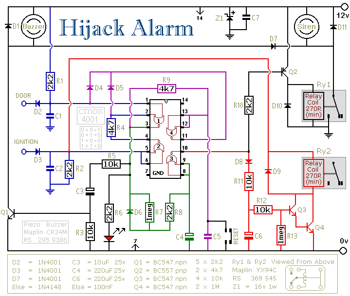
The first circuit is designed for situations where a hijacker forces the driver from the vehicle. If a door is opened while the ignition is switched on, the circuit will activate. After a few minutes delay, when the thief...
Warning: include(partials/cookie-banner.php): Failed to open stream: Permission denied in /var/www/html/nextgr/view-circuit.php on line 713
Warning: include(): Failed opening 'partials/cookie-banner.php' for inclusion (include_path='.:/usr/share/php') in /var/www/html/nextgr/view-circuit.php on line 713